Disassembly Note
- Remove the front axle assembly; see AXLE ASSEMBLY FRONT REMOVAL/INSTALLATION
,
.
- Install the axle on bench.
NOTE:
- Place a suitable drain pan under the axle.
- Drain the axle fluid.
- Remove the ten differential cover bolts.
- Remove the differential cover.
- Remove the axle shaft using a jerking motion.
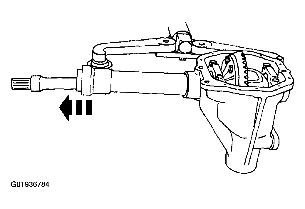 Courtesy of MAZDA MOTORS CORP.
- Use Converter Seal Remover ST
49 UN01 0870 or equivalent and Impact Slide Hammer ST
49 0223 630B and Adapter ST
49 UN11 101 to remove the LH axle seal.
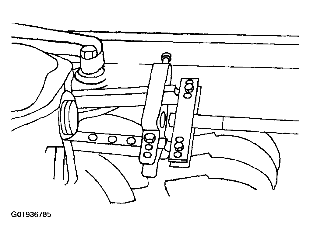 Courtesy of MAZDA MOTORS CORP.
- Use Bearing Cup Puller ST
308-047 or equivalent and Impact Slide Hammer ST
49 0223 630B and Adapter ST49 UN11 101 to remove the LH axle bearing.
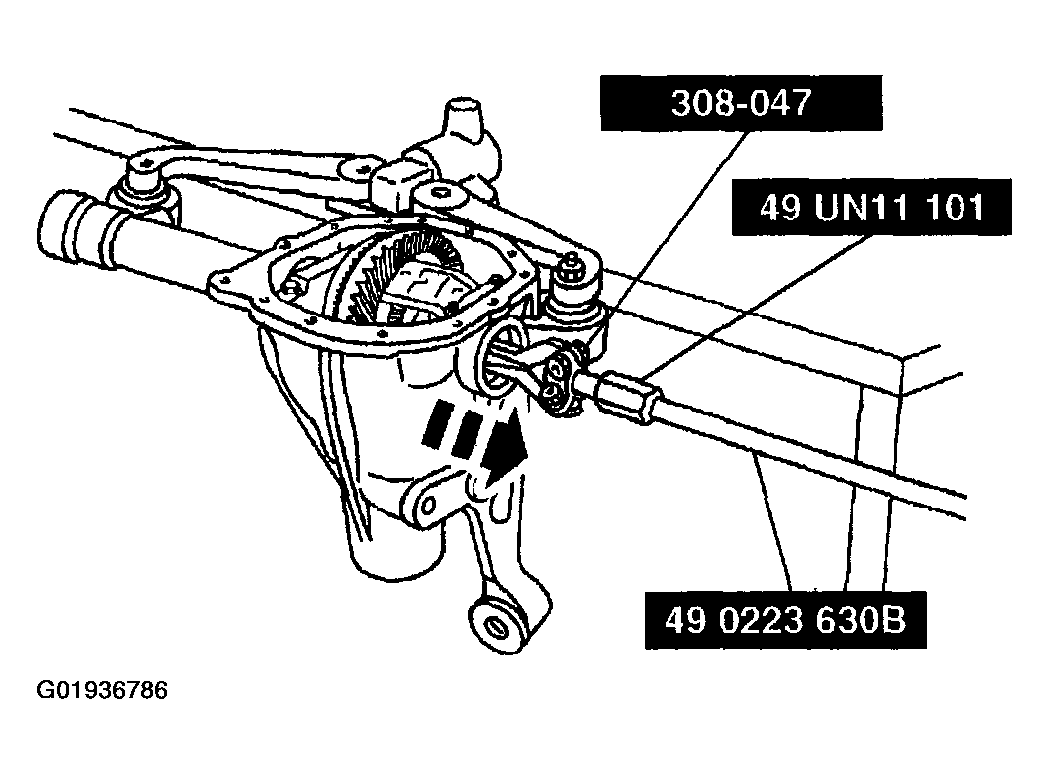 Courtesy of MAZDA MOTORS CORP.
- Use Converter Seal Remover ST
49 UN01 0870 or equivalent and Impact Slide Hammer ST
49 0223 630B and Adapter ST
49 UN11 101 to remove the RH axle shaft seal.
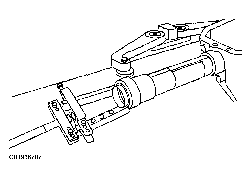 Courtesy of MAZDA MOTORS CORP.
- Use Bearing Remover ST
307-318 or equivalent and Impact Slide Hammer ST
49 0223 630B and Adapter ST
49 UN11 101 to remove the RH axle bearing.
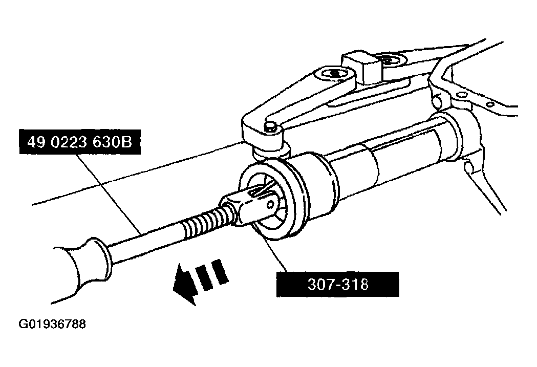 Courtesy of MAZDA MOTORS CORP.
CAUTION:
- The matched numbers or letters stamped on both of the differential bearing caps and the axle housing must correspond upon assembly.
- Remove the differential bearing caps.
- Remove the four bolts.
- Remove the two differential bearing caps.
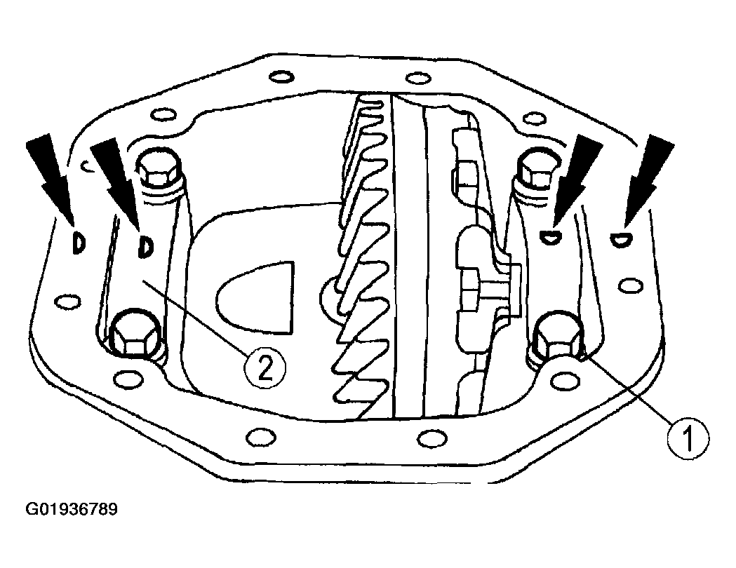 Courtesy of MAZDA MOTORS CORP.
CAUTION:
- The ST
bolts have a minimum thread engagement.
- Install Spreader Adapters ST
49 UN01 027.
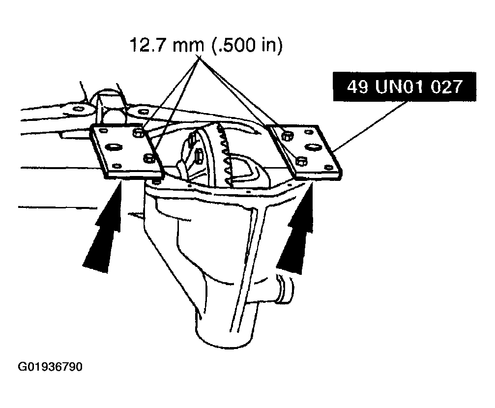 Courtesy of MAZDA MOTORS CORP.
NOTE:
- Make sure the indicator needle is in the spreader adapter hole.
- Install Differential Housing Spreader ST
49 UN01 026 and Dial Indicator with Bracketry.
- Install ST
49 UN01 026.
- Install Dial Indicator with Bracketry and Clutch Housing Alignment Adapter ST
308-021.
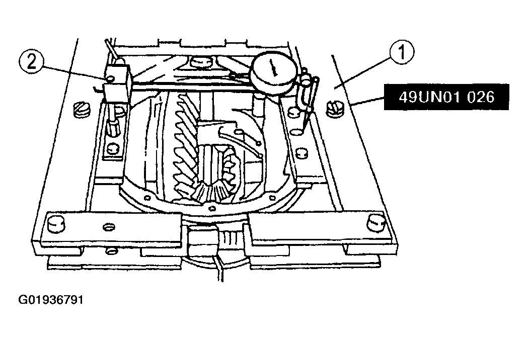 Courtesy of MAZDA MOTORS CORP.
CAUTION:
- Over-spreading may cause damage to the axle housing.
- Spread the axle housing.
- Adjust the Dial Indicator to zero.
- Tighten screw from Differential Housing Spreader ST
49 UN01 026 until the axle housing is spread.
- Remove Dial Indicator with Bracketry.
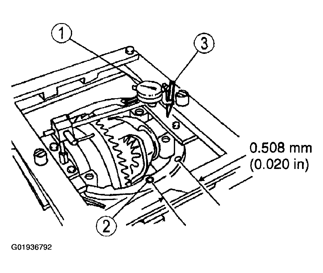 Courtesy of MAZDA MOTORS CORP.
CAUTION:
- Wood blocks must be used to avoid axle housing damage.
- Remove the differential case from the axle housing.
- Position the wood blocks.
- Use two pry bars; push down on the pry bars.
- Remove the differential case.
- Remove Differential Housing Spreader ST
49 UN01 026.
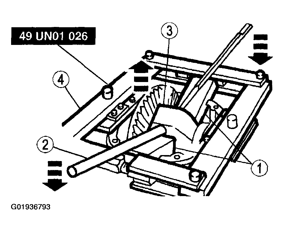 Courtesy of MAZDA MOTORS CORP.
- Measure the pinion bearing preload.
- Use a beam type torque wrench to measure the torque required to maintain rotation of the pinion and record the measure for reference during assembly.
- Index mark the companion flange to the pinion stem.
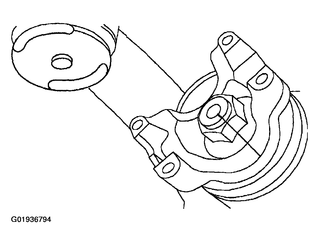 Courtesy of MAZDA MOTORS CORP.
- Use Coupling Holder ST
205-126 to hold the companion flange while removing the pinion nut.
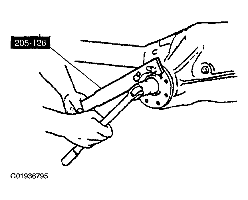 Courtesy of MAZDA MOTORS CORP.
- Use a 2-jaw puller to remove the companion flange.
WARNING:
- Gear teeth may have sharp edges. When handling gear, use care to avoid personal injury.
CAUTION:
- Use a soft mallet to drive the pinion out of the axle housing.
- Remove the pinion from the axle housing.
- Hold the pinion inside the axle housing.
- Use a soft face hammer to remove the pinion from the axle housing.
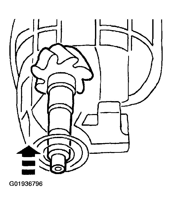 Courtesy of MAZDA MOTORS CORP.
- Use Converter Seal Remover ST
49 UN01 0870 or equivalent and Impact Slide Hammer ST
49 0223 630B and Adapter ST
49 UN11 101 to remove the pinion seal.
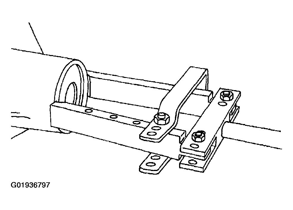 Courtesy of MAZDA MOTORS CORP.
- Remove the oil slinger (1) and the differential pinion bearing (2).
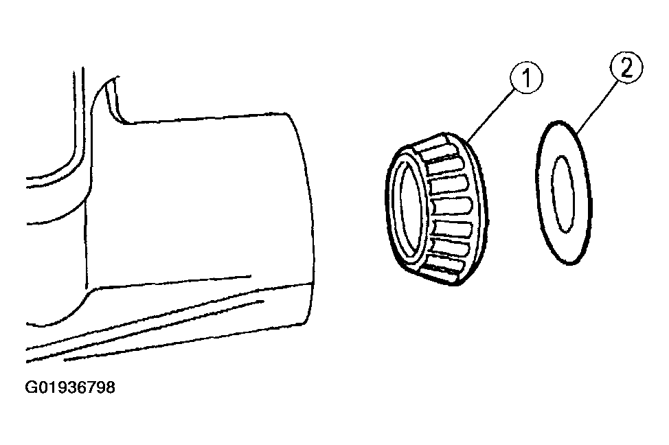 Courtesy of MAZDA MOTORS CORP.
- Remove the outer differential pinion bearing cup by tapping alternately on each side to prevent it from cocking in the bore.
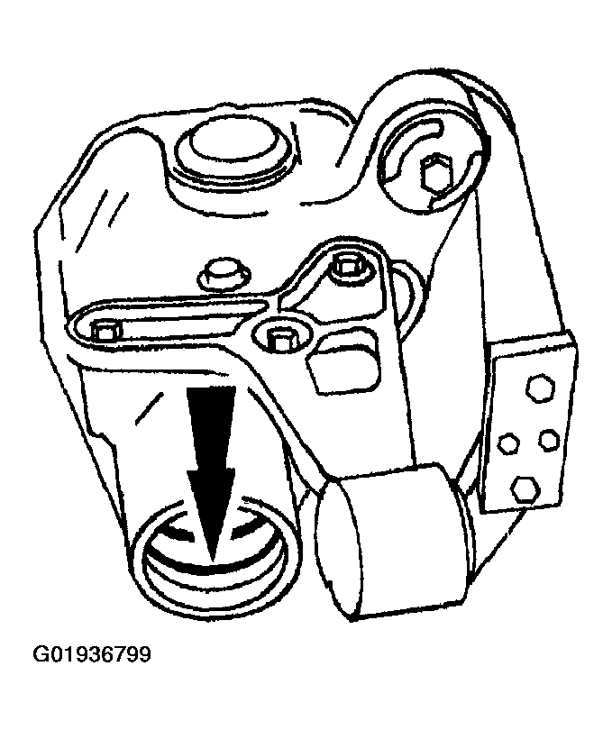 Courtesy of MAZDA MOTORS CORP.
- Remove the inner differential pinion bearing cup by tapping alternately on each side to prevent it from cocking in the bore.
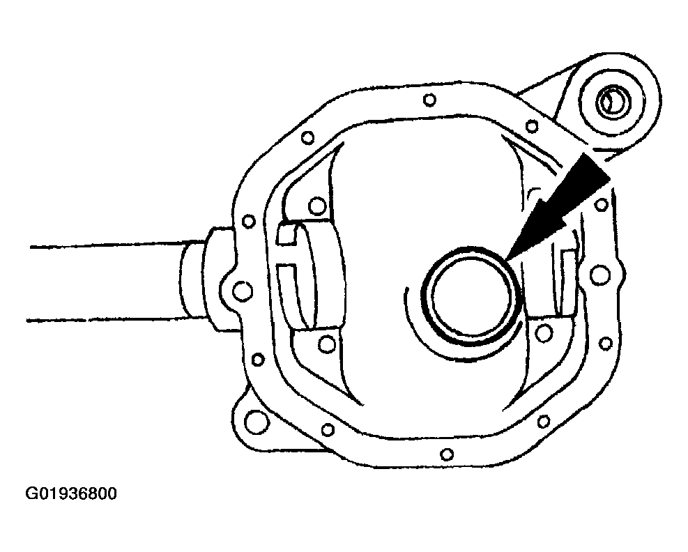 Courtesy of MAZDA MOTORS CORP.
- Remove the differential pinion bearing.
- Install the Pinion Bearing Cone Remover 205-055 or equivalent on the differential pinion bearing assembly.
- Position the Pinion Bearing Cone Remover 205-055 or equivalent and the differential pinion bearing assembly in a press.
- Press the differential pinion bearing off.
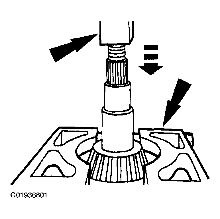 Courtesy of MAZDA MOTORS CORP.
NOTE:
- Measure the pinion position shim with a micrometer and record the thickness (use this as a reference to compare the shim gauge reading prior to installing the differential pinion bearing).
- Remove the pinion position shim from the differential pinion gear.
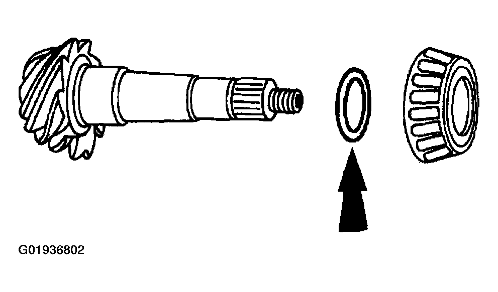 Courtesy of MAZDA MOTORS CORP.
- Remove the ring gear.
- Remove the eight bolts.
- Use a drift punch to separate the ring gear from the differential case.