Arming Sequence Verification
- Start vehicle, turn ignition switch to OFF position, to ensure alarm is reset. Close all doors. If warning light is off, go to step 2). If warning light is on steady, go to step 10).
- Open a vehicle door. If warning light blinks, go to step 3). If warning light does not blink, go to step 6).
- Activate an electric door lock switch, or simultaneously press buttons No. 7 and 9 of the keyless entry panel. If warning light is on steady, go to step 4). If warning light blinks, go to step 8).
- Close vehicle door. Check that warning light shuts off after 32 seconds. On all models except Town Car, if warning light shuts off, arming sequence is okay. If warning light stays on, replace control module and retest system. On Town Car, if warning light shuts off, verify that alarm is not triggered. If alarm is triggered, see FALSE TRIGGERING
test in this article. If alarm is not triggered, arming sequence is okay.
- Check voltage at terminal No. 3 of control module. See Fig 1
. If voltage is greater than 5 volts, replace control module and retest system. If voltage less than 2 volts, verify all doors are closed. Check door jam switches and circuit No. 627 (Black/Orange) wire for short.
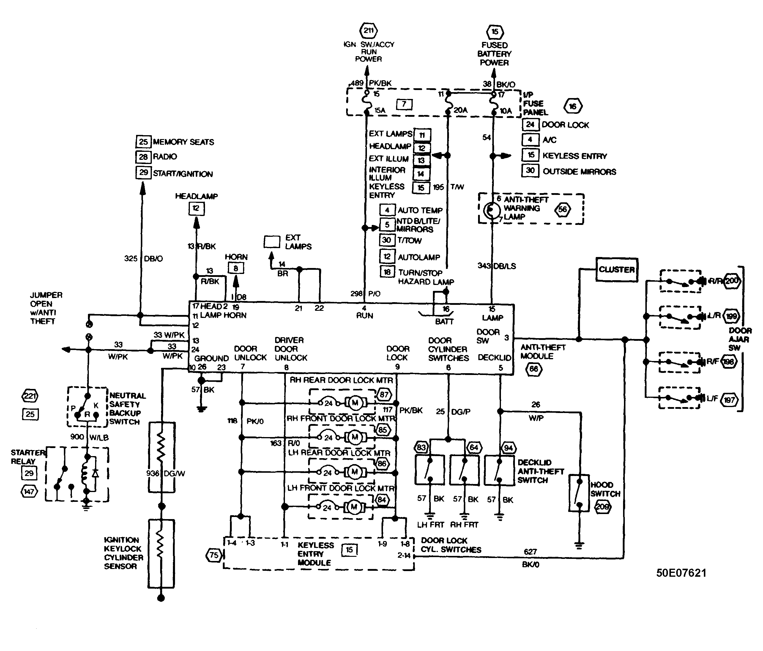 Courtesy of FORD MOTOR CO.
- Check voltage on terminal No. 3 of control module.
- If reading is less than 2 volts, disconnect control module wiring harness. Apply a ground to harness connector pin No. 15, warning light should come on. If warning light comes on, replace control module. If warning light does not come on, check warning light bulb or circuit No. 343 (Dark Blue/Light Green) wire. If reading is more than 5 volts, check door jam switches or circuit No. 627 (Black/Orange) wire.
- Check to see if doors locked. If doors locked, go to step 9). If doors did not lock, see ELECTRIC DOOR LOCK or KEYLESS ENTRY SYSTEM article. 9 Check voltage at door unlock terminal No. 7, circuit No. 118 (Pink/Orange) wire. Check for a momentary battery voltage signal at terminal No. 9, circuit No. 117 (Pink/Black) wire of control module when door lock switch is activated. If momentary battery voltage signal is present, go to step 11). If voltage at terminal No. 7 is less than 2 volts, check circuit No. 117 (Pink/Black) wire or circuit No. 118 (Pink/Orange) wire and retest system.
- Disconnect harness connector from control module. If warning light is still on, check circuit No. 343 (Dark Blue/Light Green) wire for short and retest system. If warning light goes off, replace control module and retest system.
- Check voltage at pin No. 6 of control module. If reading is more than 5 volts, replace control module and retest system. If reading is less than 2 volts, check driver's and passenger's door disarm switches and circuit No. 25 (Dark Green/Purple) wire for short. Retest system.