Test C: Passenger's Power Window Inoperative
- Turn ignition switch to LOCK position. Remove passenger's power door lock/window switch. See REMOVAL & INSTALLATION
. Disconnect passenger's power door lock/window switch Black 10-pin harness connector C600. Turn ignition switch to RUN position. Measure voltage between ground and passenger's power door lock/window switch Black 10-pin harness connector C600 terminal No. 3 (Red/Light Blue wire). See Fig 1
. If voltage is more than 10 volts, go to next step. If voltage is 10 volts or less, repair open in Red/Light Blue wire between passenger's power door lock/window switch Black 10-pin harness connector C600 and Central Junction Box (CJB) fuse No. 43. See WIRING DIAGRAMS
. Retest system operation.
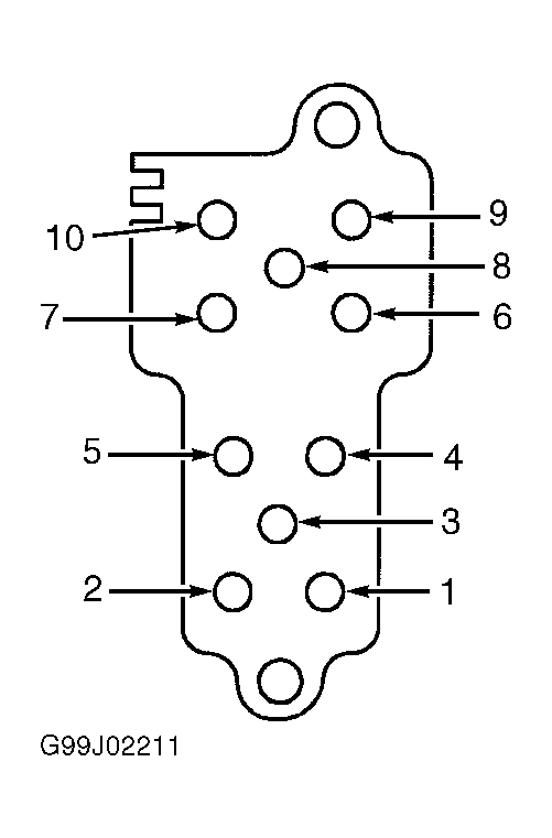 Courtesy of FORD MOTOR CO.
- Turn ignition switch to LOCK position. Remove master window/door lock control switch. See REMOVAL & INSTALLATION
. Disconnect master window/door lock control switch Black 15-pin harness connector C500. Turn ignition switch to RUN position. Measure voltage between ground and master window/door lock control switch Black 15-pin harness connector C500 terminal No. 11 (Red/Light Blue wire). See Figure
. If voltage is more than 10 volts, go to next step. If voltage is 10 volts or less, repair open in Red/Light Blue wire between master window/door lock control switch Black 15-pin harness connector C500 and CJB fuse No. 43. See WIRING DIAGRAMS
. Retest system operation.
- Turn ignition switch to LOCK position. Measure resistance between ground and, in turn, master window/door lock control switch Black 15-pin harness connector C500 terminals No. 9 and 14 (Black wires). See Figure
. If both resistance measurements are less than 5 ohms, go to next step. If either resistance measurement is 5 ohms or more, repair open in Black wire(s) between ground and appropriate master window/door lock control switch Black 15-pin harness connector C500 terminal. See WIRING DIAGRAMS
. Retest system operation.
- Reconnect master window/door lock control switch Black 15-pin harness connector C500. Turn ignition switch to RUN position. Measure voltage between passenger's power door lock/window switch Black 10-pin harness connector C600 terminals No. 2 (Tan/Light Blue wire) and No. 4 (White/Yellow wire) while operating master window/door lock control switch in UP position, then in DOWN position. If voltage is more than 10 volts in both measurements, go to next step. If voltage is 10 volts or less in either measurement, check for open or short to ground in Tan/Light Blue and/or White/Yellow wire between master window/door lock control switch Black 15-pin harness connector C500 and passenger's power door lock/window switch Black 10-pin harness connector C600. See WIRING DIAGRAMS
. Repair as necessary. Retest system operation. If wires are okay, replace master window/door lock control switch. Retest system operation.
- Turn ignition switch to LOCK position. Reconnect passenger's power door lock/window switch Black 10-pin harness connector C600. Disconnect passenger's power window motor 2-pin harness connector. Turn ignition switch to RUN position. Measure voltage between passenger's power window motor 2-pin harness connector Red/Yellow wire and Yellow/Red wire terminals, while operating passenger's power window switch in UP position, then in DOWN position. If voltage is 10 volts or less in either measurement, check for open or short to ground in Red/Yellow and/or Yellow/Red wire between passenger's power window switch 10-pin harness connector C600 and passenger's power window motor 2-pin harness connector. See WIRING DIAGRAMS
. Repair as necessary. Retest system operation. If wires are okay, replace passenger's power window motor. See REMOVAL & INSTALLATION
. Retest system operation.