Checking Powertrain Control Module Power & Ground Circuits (Ram Pickup)
- Turn ignition off. Disconnect Black PCM connector C1. PCM is located at rear of engine compartment on firewall. Inspect connector for damaged pins, corrosion and loose terminals. Repair connector as necessary. Using 12-volt test light connected to ground, probe PCM harness connector C1 terminal A22 (Red/White wire). See Fig 1
. If test light illuminates brightly, go to next step. If test light does not illuminate brightly, check for open in Red/White wire between Power Distribution Center (PDC) and PCM, or for blown fuse No. 18 (20-amp) in PDC. See Fig 2
. PDC is located on left side of engine compartment. Repair wiring or replace fuse as necessary. See WIRING DIAGRAMS article.
- Turn ignition on. Using 12-volt test light connected to ground, probe PCM harness connector C1 terminal A2 (Light Green/Black wire). See Fig 1
. If test light illuminates brightly, power circuits are okay. Go to next step. If test light does not illuminate brightly, repair open in Light Green/Black wire between PCM and junction block, or for blown fuse No. 9 (10-amp) in junction block. Junction block is located behind left kick panel. Repair wiring or replace fuse as necessary.
- Turn ignition off. Using 12-volt test light connected to positive battery voltage, probe PCM harness connector C1 terminals A31 and A32 (Black/Tan wires). See Fig 1
. If test light illuminates brightly at both terminals, go to next step. If test light does not illuminate brightly at one or both terminals, repair open in appropriate Black/Tan wire between PCM and ground point. Ground point is located on front of engine.
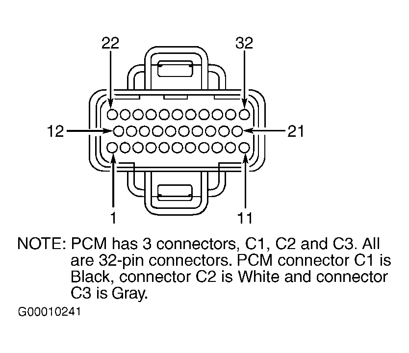 Courtesy of DAIMLERCHRYSLER CORPORATION
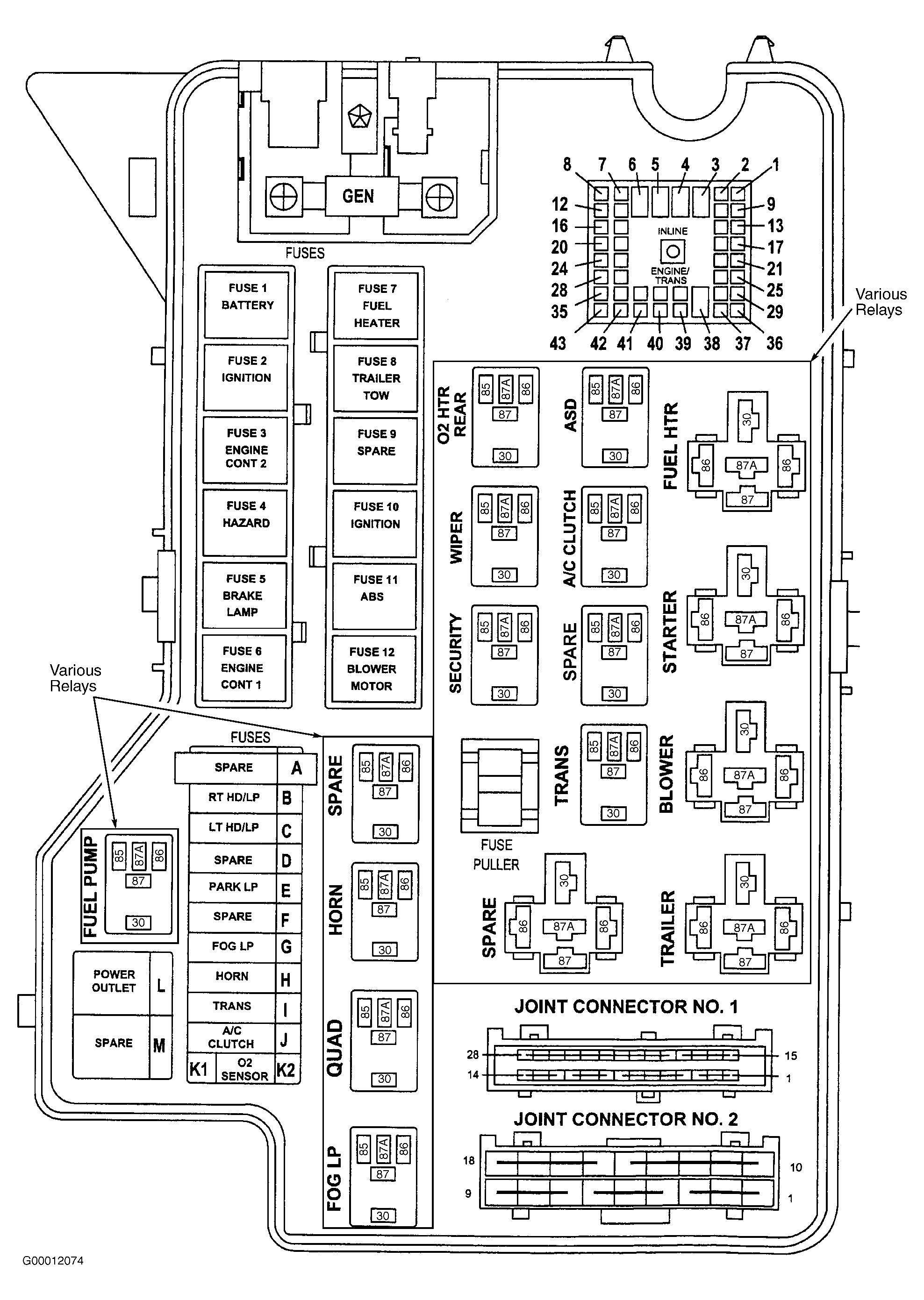 Courtesy of DAIMLERCHRYSLER CORPORATION