Engine 4.6L: Removal: Engine
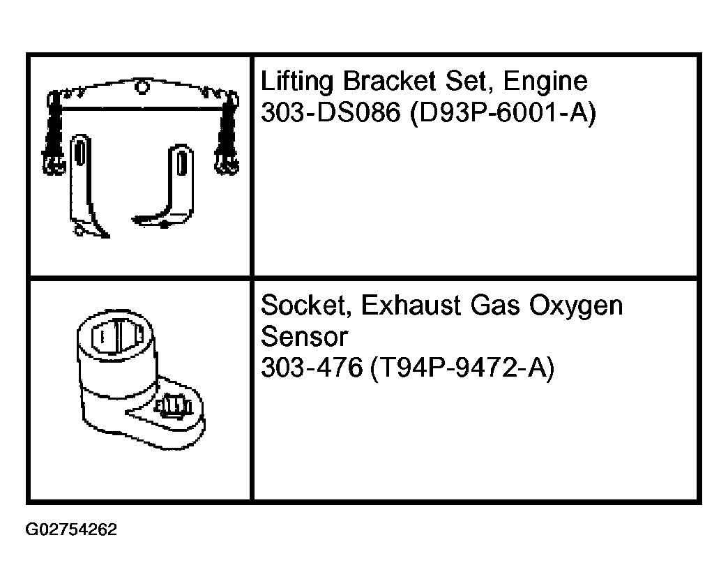 Courtesy of FORD MOTOR CO.
- Remove the hood.
- Disconnect both battery cables. For additional information, refer to BATTERY, MOUNTING AND CABLES
.
- Remove the air cleaner and outlet pipe. For additional information, refer to INTAKE AIR DISTRIBUTION & FILTERING
.
- Remove the wiper mounting arm and pivot shaft. For additional information, refer to WIPERS AND WASHERS
.
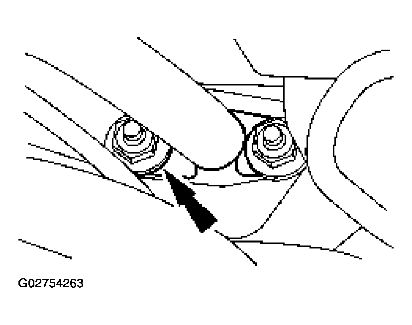
- Remove the support bracket.
 Courtesy of FORD MOTOR CO.
- Remove the accessory drive belt. For additional information, refer to SPECIFICATIONS & DRIVE BELT ROUTING
.
- Drain the engine cooling system. For additional information, refer to ENGINE COOLING
.
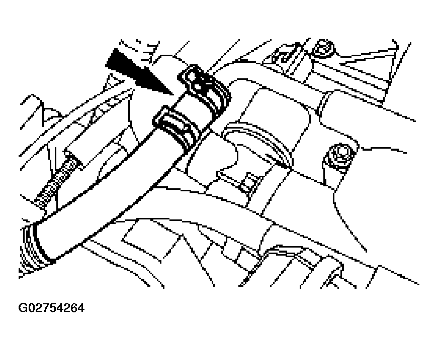
- Disconnect the vacuum hose.
 Courtesy of FORD MOTOR CO.
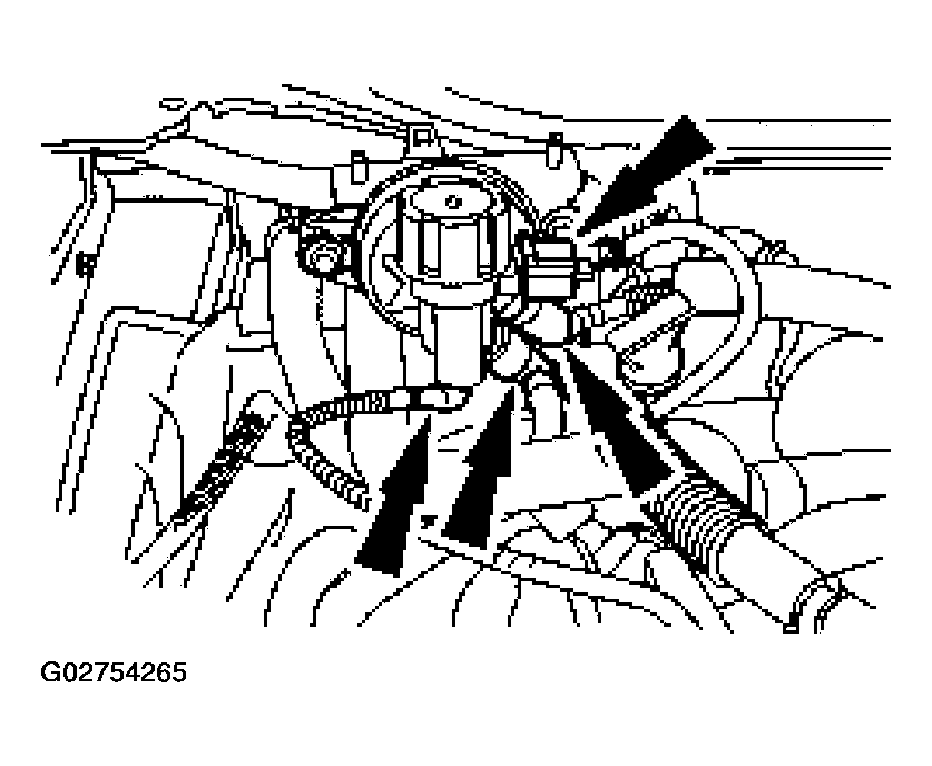
- Remove the evaporative emission (EVAP) canister purge valve.
- Disconnect the three hoses.
- Disconnect the electrical connector.
 Courtesy of FORD MOTOR CO.
- Disconnect the accelerator cable and the speed control actuator cable.
- Remove the bolts.
- Disconnect the cables.
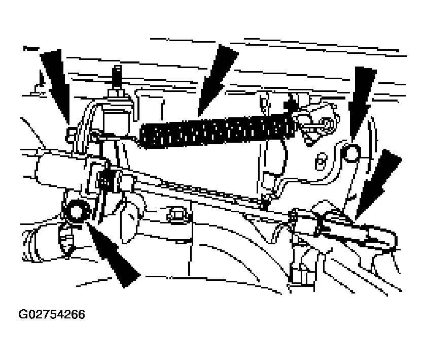 Courtesy of FORD MOTOR CO.
- Remove the accelerator cable and the speed control actuator cable from the clips and position out of the way.
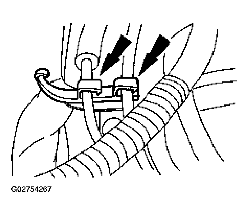 Courtesy of FORD MOTOR CO.
- Disconnect the fuel spring lock connector. For additional information, refer to FUEL SYSTEM-GENERAL INFORMATION
.
- Disconnect the electrical connectors.
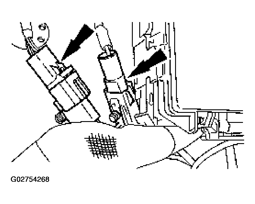 Courtesy of FORD MOTOR CO.
- Remove the electrical connection cover.
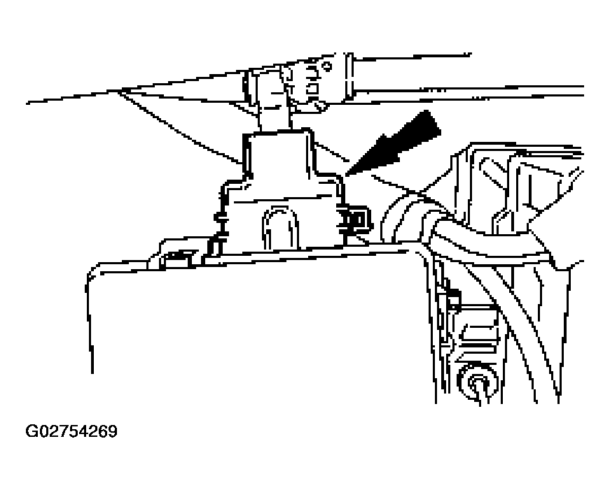 Courtesy of FORD MOTOR CO.
- Disconnect the power distribution power supply electrical connector.
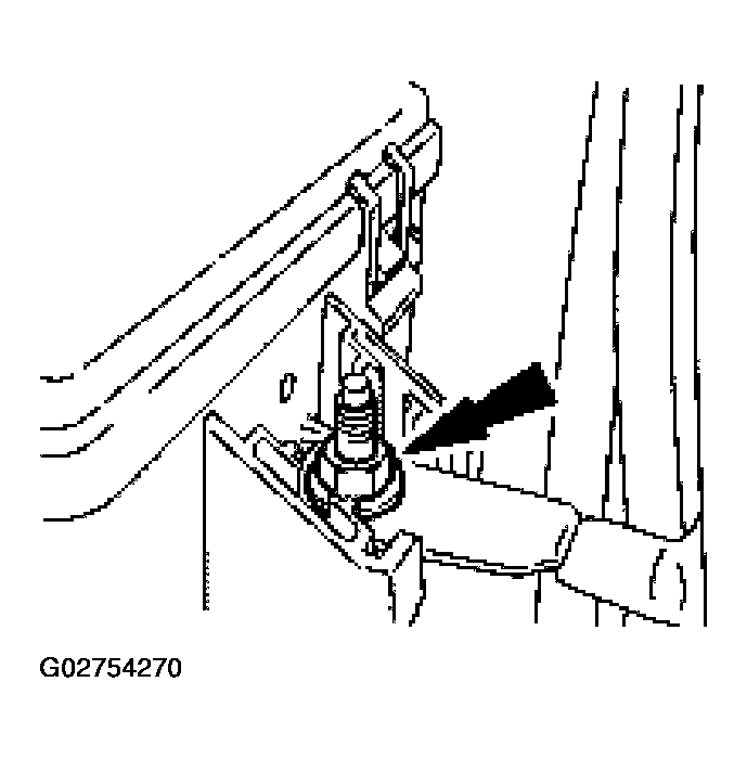 Courtesy of FORD MOTOR CO.
- Disconnect the ground wire.
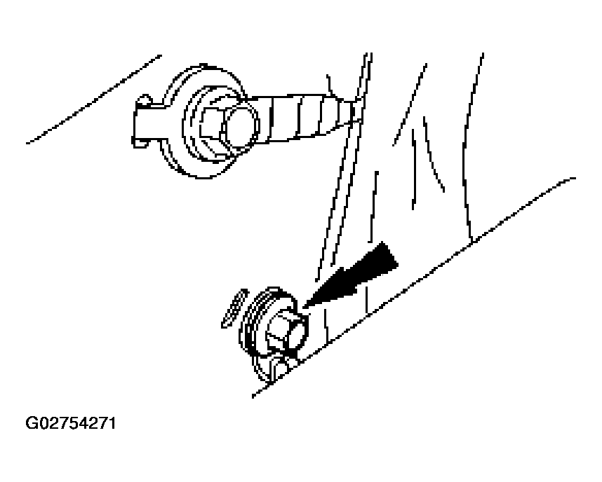 Courtesy of FORD MOTOR CO.
- Disconnect the A/C electrical connector.
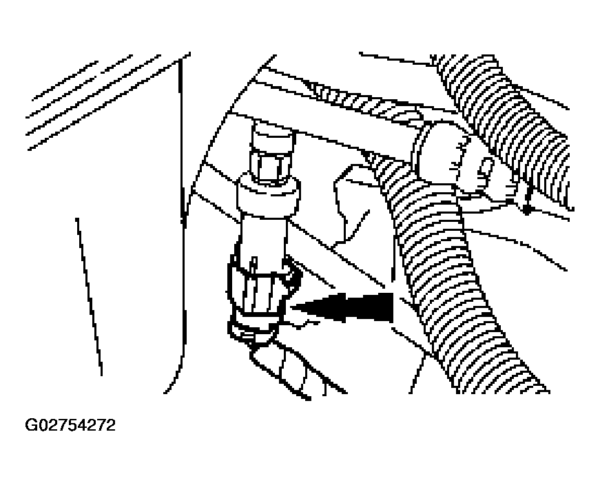 Courtesy of FORD MOTOR CO.
- Disconnect the A/C low charge protection switch electrical connector.
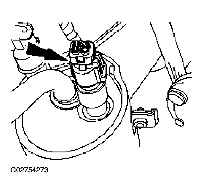 Courtesy of FORD MOTOR CO.
- Disconnect the heater hoses.
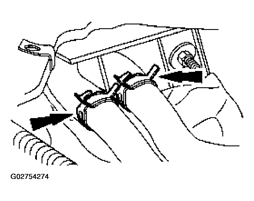 Courtesy of FORD MOTOR CO.
- Remove the ground strap.
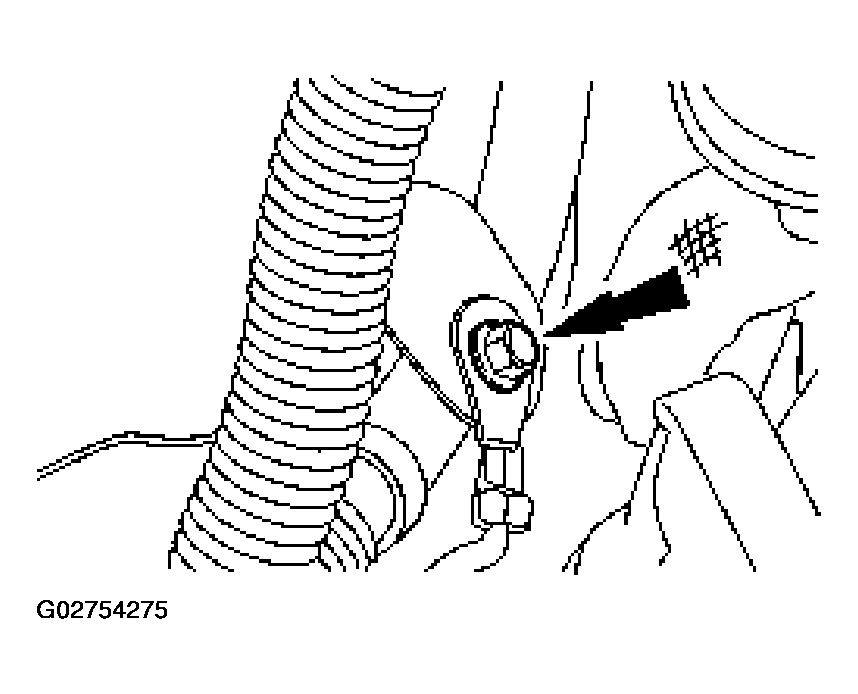 Courtesy of FORD MOTOR CO.
- Disconnect the engine bulkhead connectors.
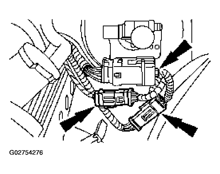 Courtesy of FORD MOTOR CO.
- Remove the bolt and position the power steering pump reservoir aside.
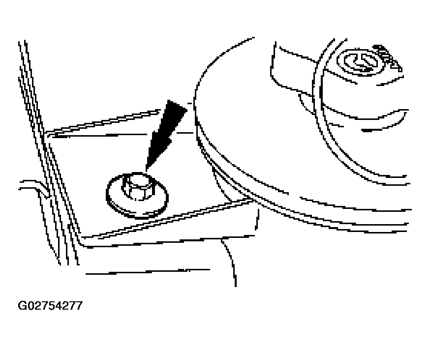 Courtesy of FORD MOTOR CO.
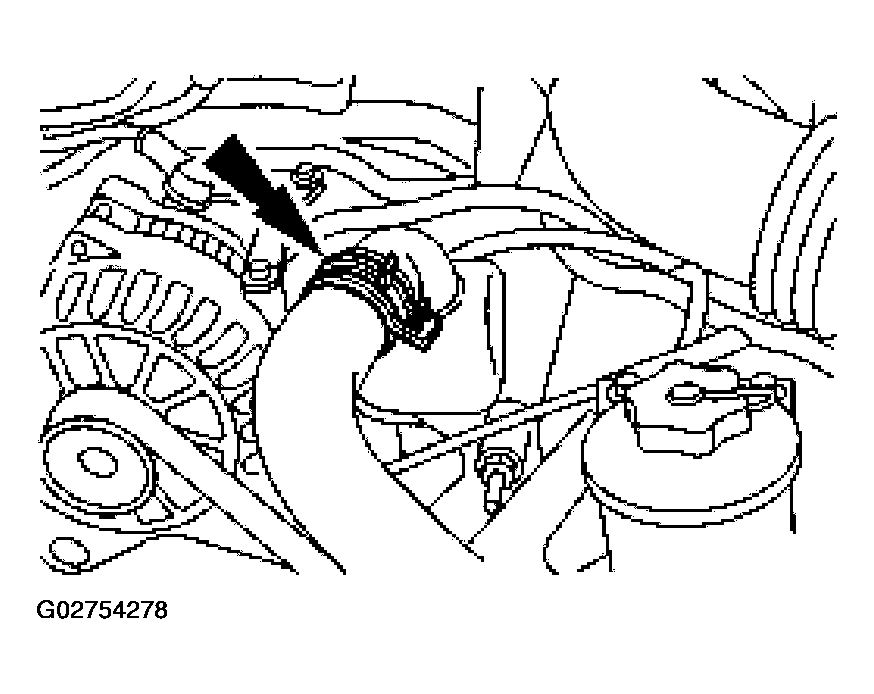
- Disconnect the upper radiator hose from the hose connection. Secure the hose to the radiator assembly.
 Courtesy of FORD MOTOR CO.
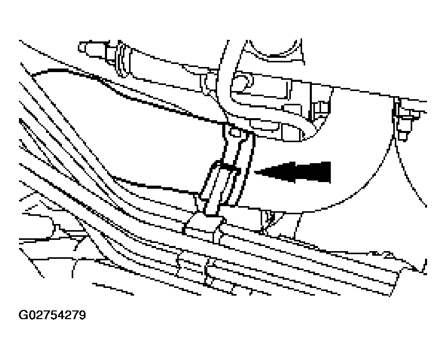
- Disconnect the lower radiator hose from the oil filter adapter.
 Courtesy of FORD MOTOR CO.
- Remove the cooling fan. For additional information, refer to ENGINE COOLING
.
- Raise and support the vehicle. For additional information, refer to JACKING & LIFTING
.
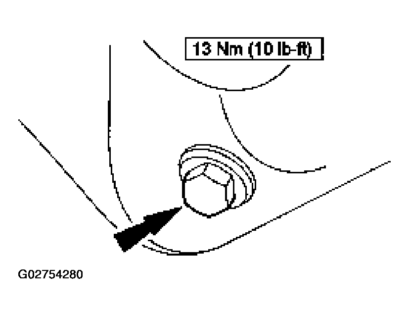
- Drain the engine oil.
- Install the drain plug when finished.
 Courtesy of FORD MOTOR CO.
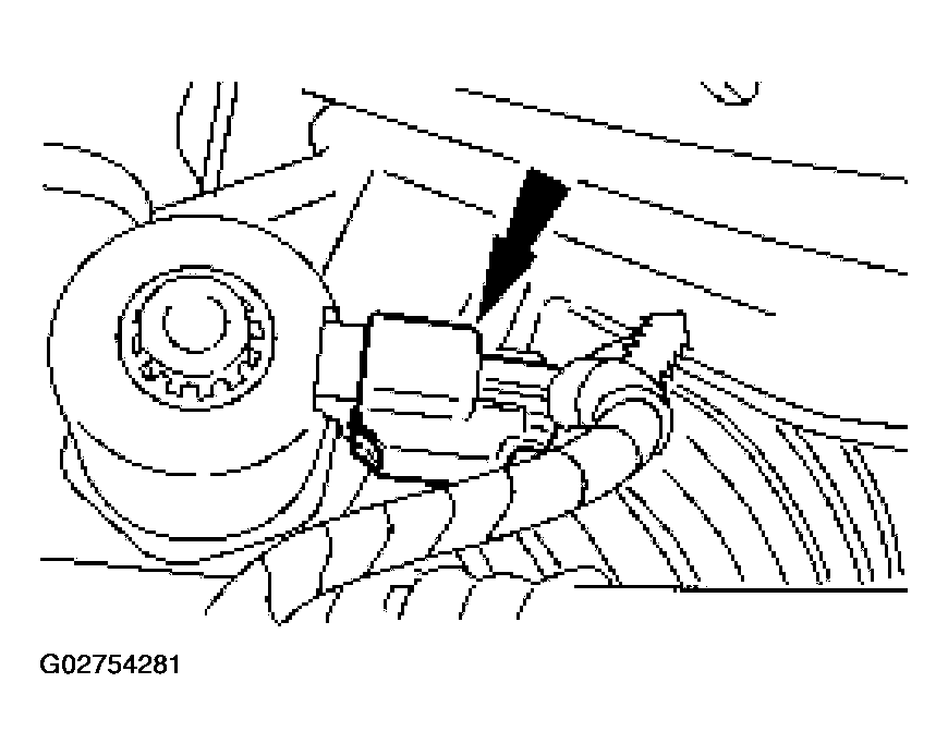
- Disconnect the power steering electrical connector.
 Courtesy of FORD MOTOR CO.
- Disconnect the electrical connector.
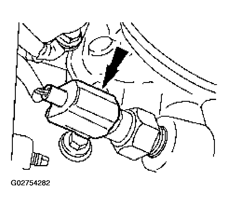 Courtesy of FORD MOTOR CO.
- Disconnect the power steering pressure (PSP) switch electrical connector.
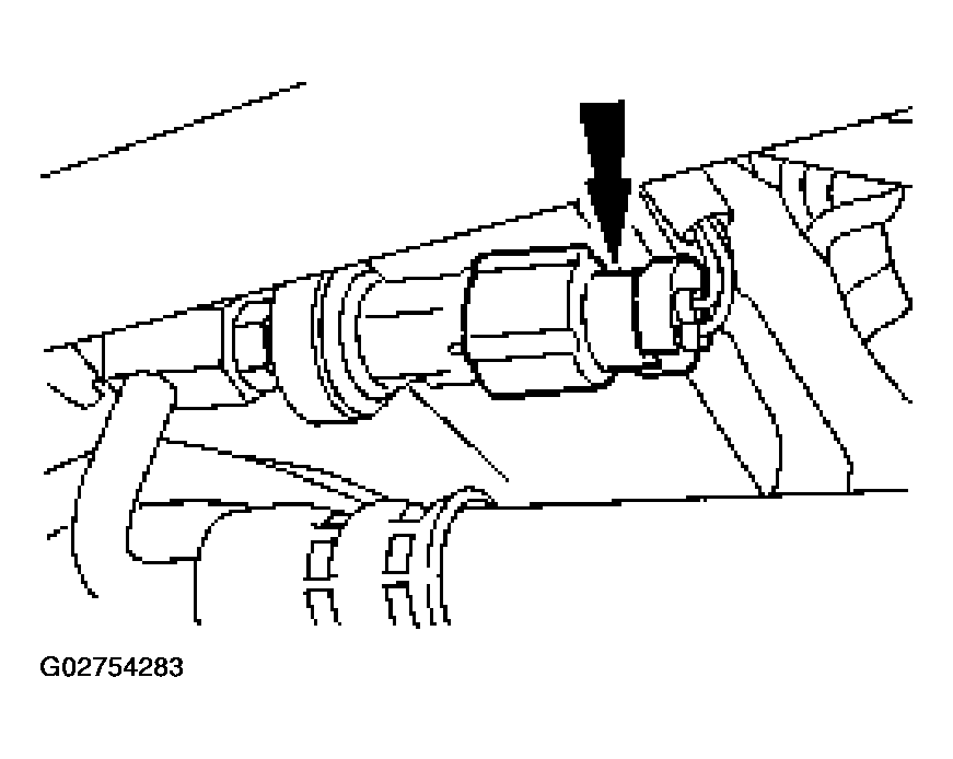 Courtesy of FORD MOTOR CO.
- Remove the nut and the transmission cooler tube support bracket.
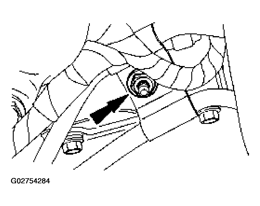 Courtesy of FORD MOTOR CO.
- Remove the bolt.
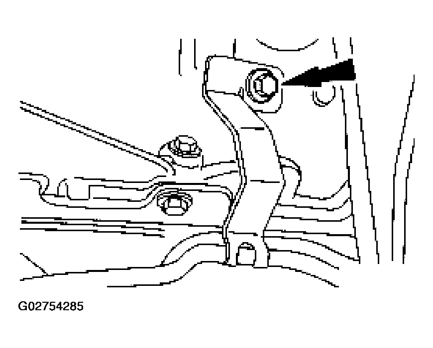 Courtesy of FORD MOTOR CO.
- Disconnect the crankshaft position (CKP) sensor electrical connector.
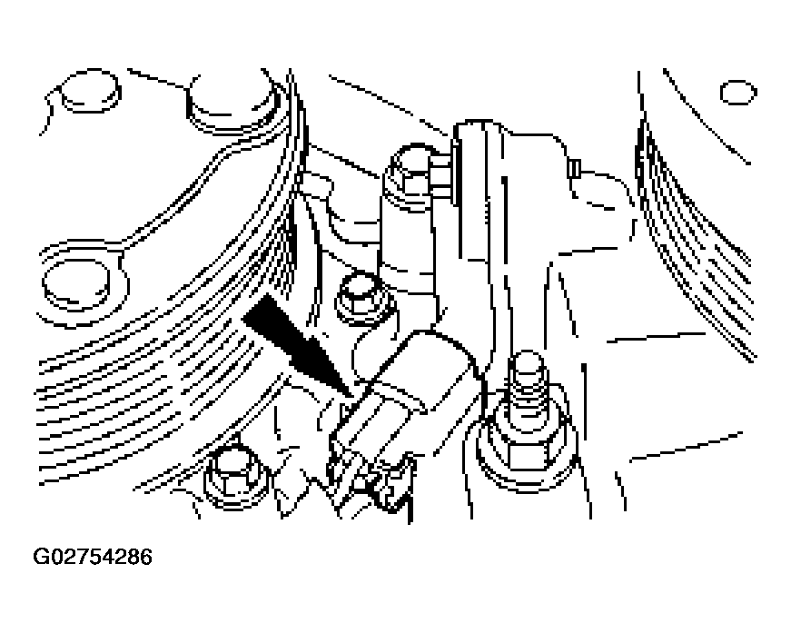 Courtesy of FORD MOTOR CO.
- Position the power steering line bracket aside.
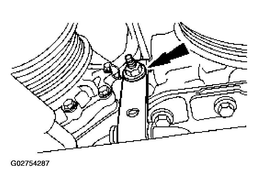 Courtesy of FORD MOTOR CO.
- Disconnect the engine wiring harness retainers from the A/C compressor.
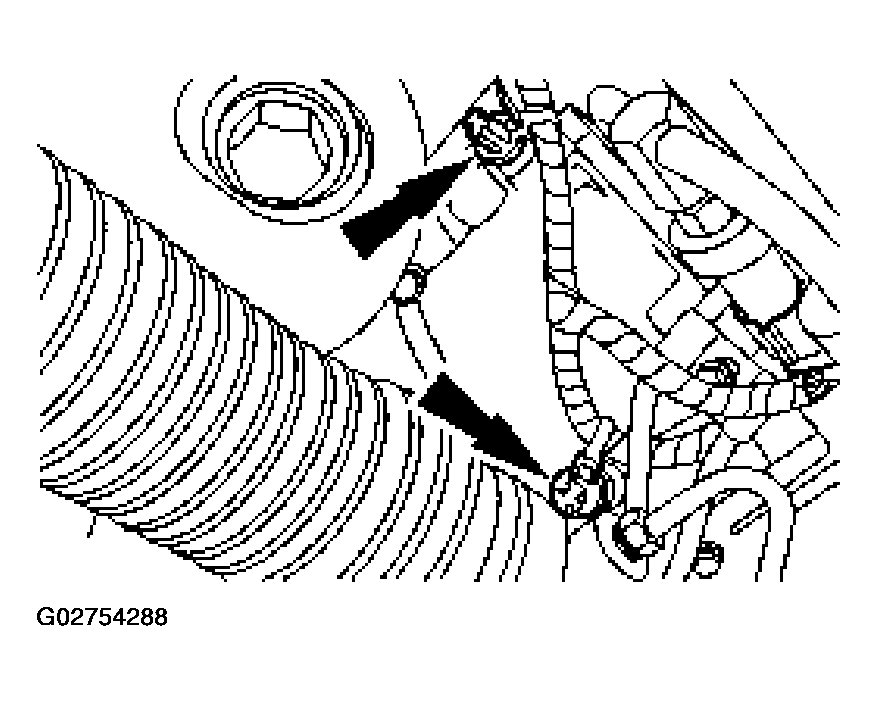 Courtesy of FORD MOTOR CO.
- Disconnect the A/C compressor electrical connector.
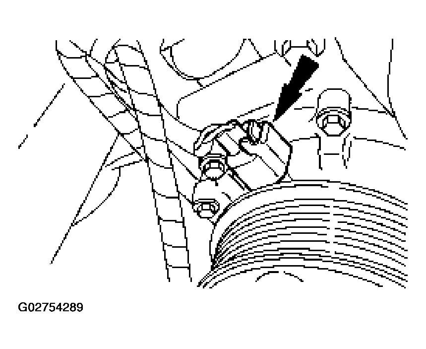 Courtesy of FORD MOTOR CO.
- Remove the four bolts and position the A/C compressor aside.
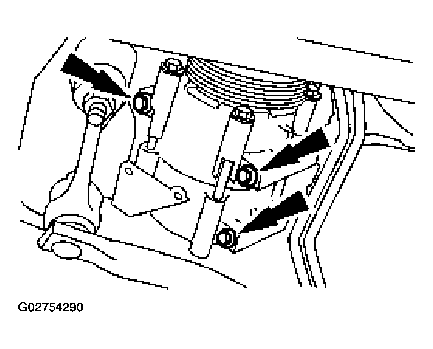 Courtesy of FORD MOTOR CO.
- Remove the bolts and position the power steering pump aside.
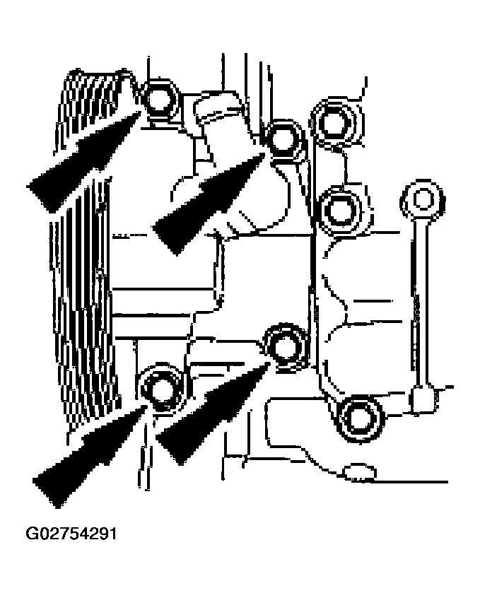 Courtesy of FORD MOTOR CO.
- Remove the starter motor.
- Remove the starter motor solenoid cover.
- Disconnect the electrical connections.
- Remove the bolts.
- Remove the starter motor.
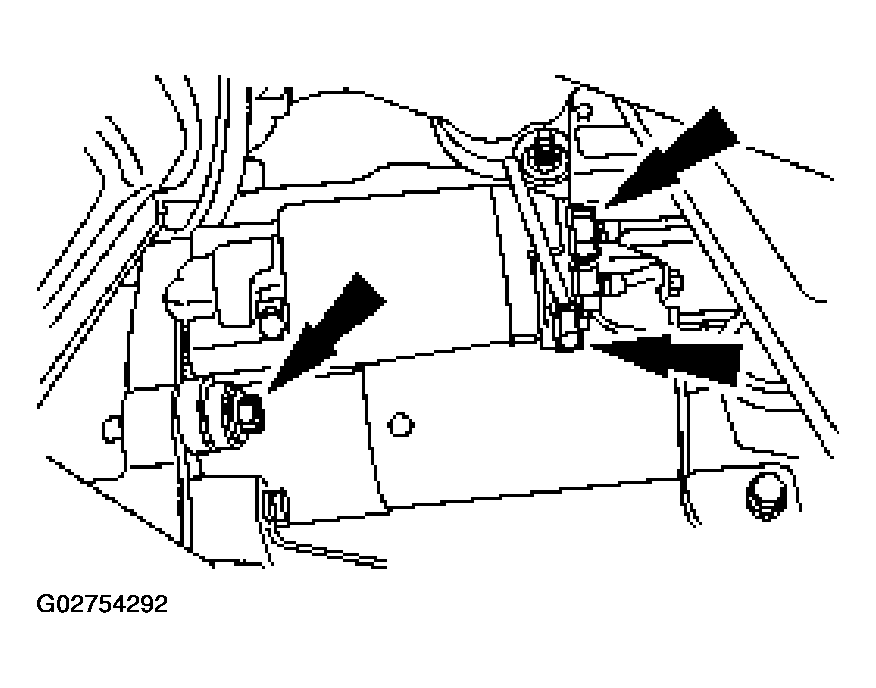 Courtesy of FORD MOTOR CO.
- Disconnect the transmission electrical connectors and the RH heated oxygen sensor electrical connectors.
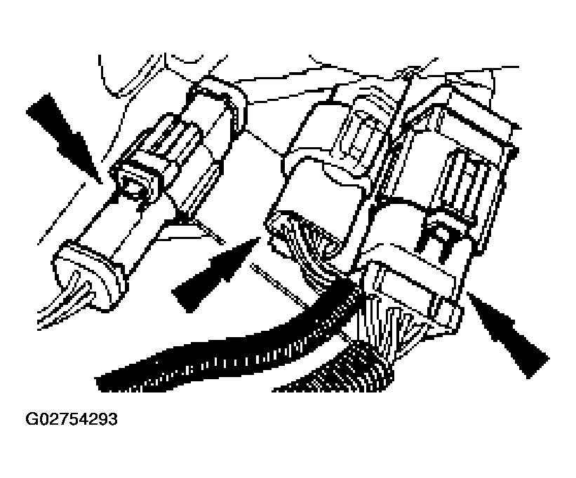 Courtesy of FORD MOTOR CO.
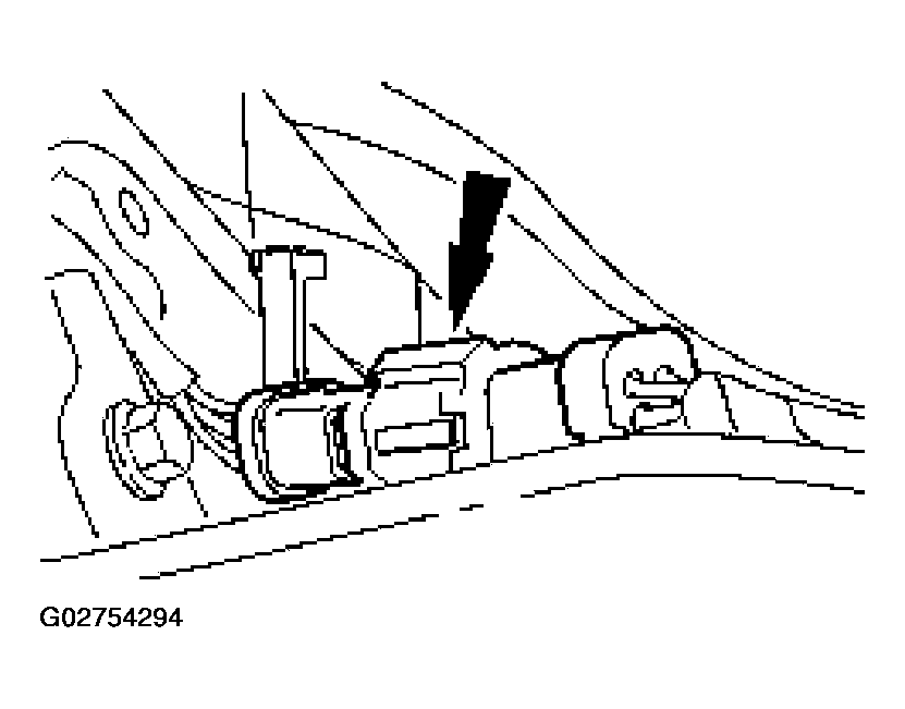
- Disconnect the LH heated oxygen sensor electrical connector.
 Courtesy of FORD MOTOR CO.
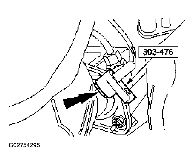
- Using the special tool, remove the LH heated oxygen sensor.
 Courtesy of FORD MOTOR CO.
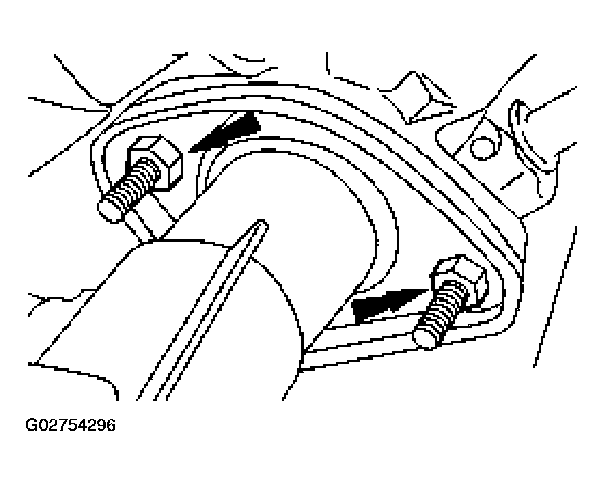
- Support the exhaust and remove the four nuts.
 Courtesy of FORD MOTOR CO.
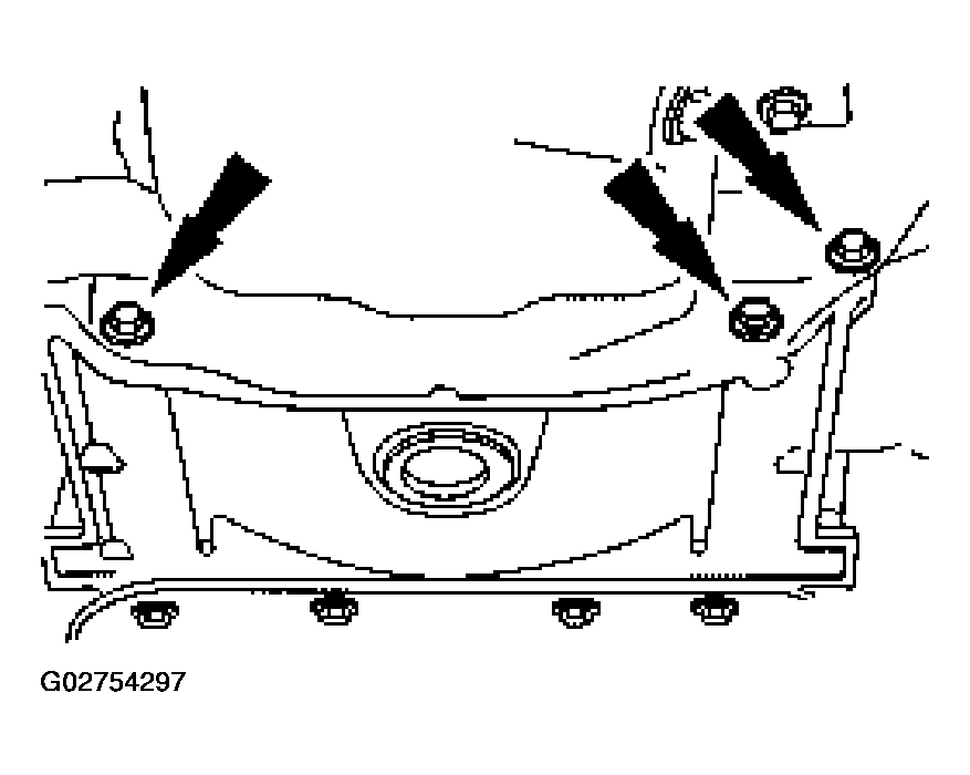
- Remove the bolts and the inspection cover.
 Courtesy of FORD MOTOR CO.
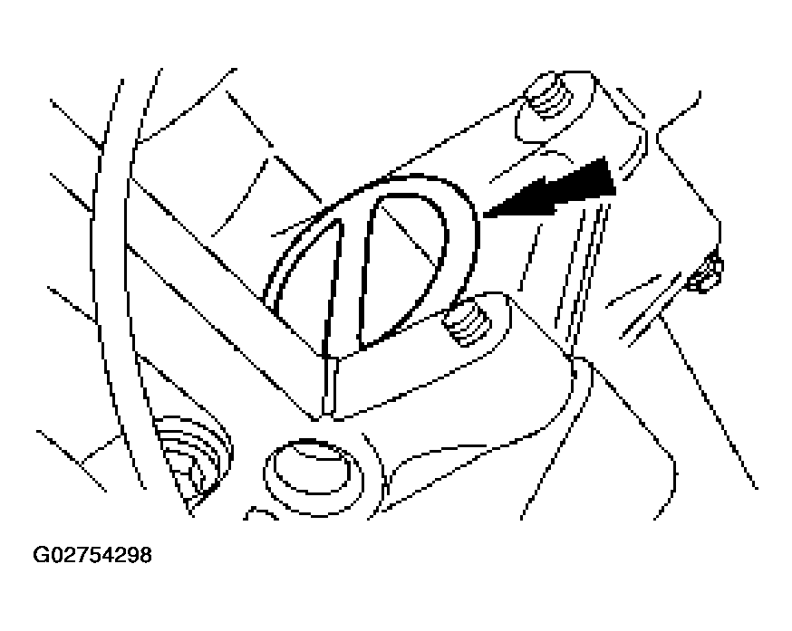
- Remove the torque converter nut access plug.
 Courtesy of FORD MOTOR CO.
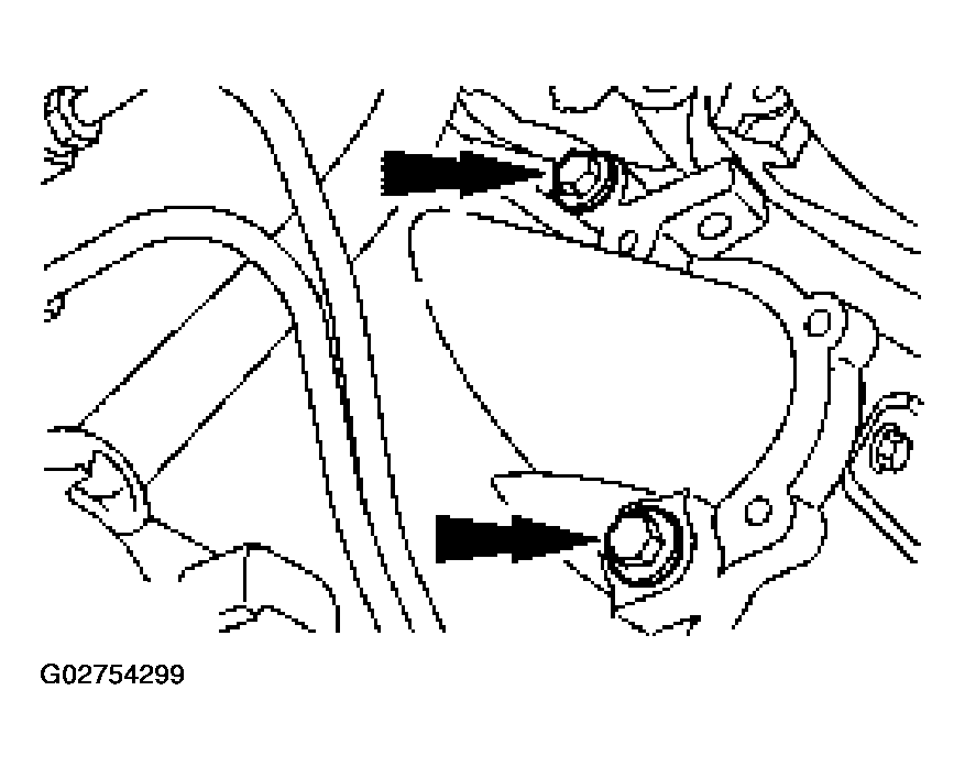
- Remove the four bolts and one stud.
 Courtesy of FORD MOTOR CO.
- Remove the engine support insulator nuts.
- Lower the vehicle.
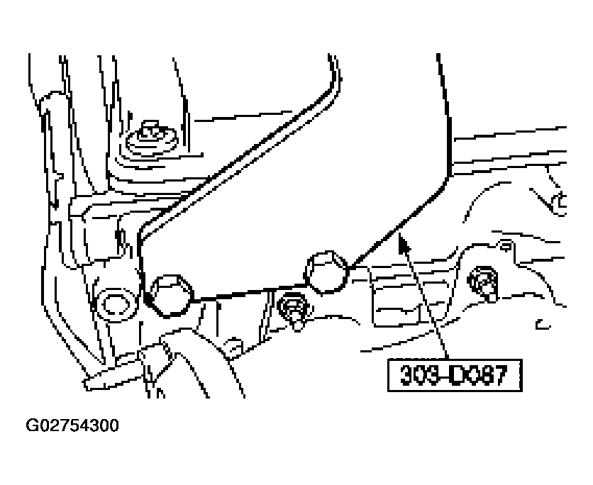
- Install the special tool to the RH cylinder head.
 Courtesy of FORD MOTOR CO.
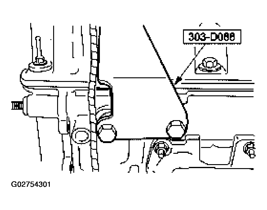
- Install the special tool to the LH cylinder head.
 Courtesy of FORD MOTOR CO.
- Install the special tools.
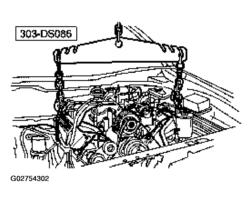 Courtesy of FORD MOTOR CO.
- Support the transmission.
- Remove the bolts.
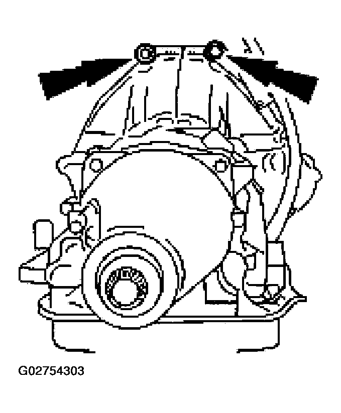 Courtesy of FORD MOTOR CO.
- Remove the engine assembly from the vehicle.
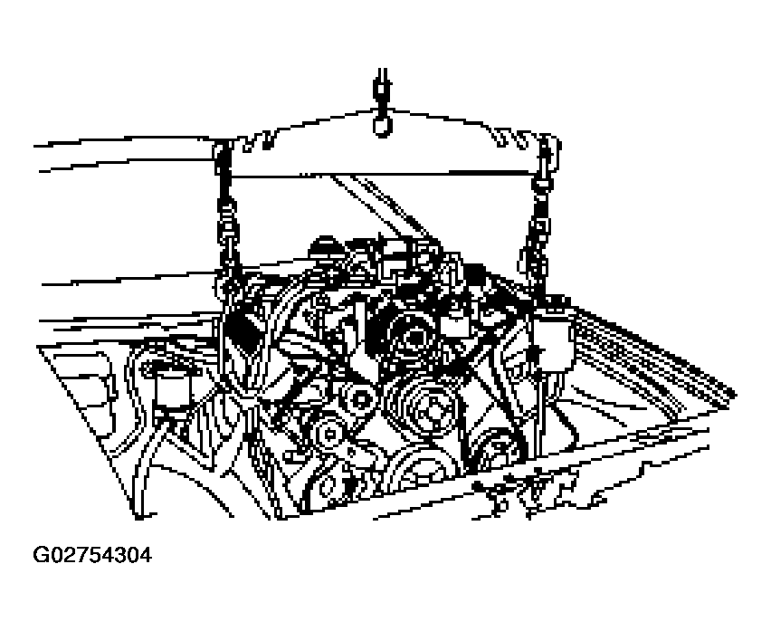 Courtesy of FORD MOTOR CO.