Models With Navigation System
- Turn ignition off. Disconnect ambient temperature sensor connector. See Figure
. Turn ignition on. Measure voltage between ambient temperature sensor harness connector terminal No. 1 (Blue/Red wire) and ground. If about 5 volts are present, go to next step. If about 5 volts are not present, go to step 4
.
- Turn ignition off. Disconnect display/navigation control unit harness connector. Check continuity of Green/White wire between display/navigation control unit harness connector terminal No. 9 and ambient temperature sensor harness connector terminal No. 2. See Fig 1
. If continuity is present, go to next step. If continuity is not present, repair wiring harness or connector as necessary. See WIRING DIAGRAMS
.
- Check ambient temperature sensor resistance. See AMBIENT TEMPERATURE SENSOR, INTAKE SENSOR & IN-VEHICLE TEMPERATURE SENSOR RESISTANCE
table. If resistances are not to specification, replace ambient temperature sensor. If resistances are to specification, replace display/navigation control unit. Perform self-diagnosis step 2 and ensure code No. 20 is displayed. See SELF-DIAGNOSIS STEP 2
under SELF-DIAGNOSTICS.
- Disconnect display/navigation control unit harness connector. See Figure
. Check continuity of Blue/Red wire between A/C auto amplifier harness connector terminal No. 2 and ambient temperature sensor harness connector terminal No. 1. If continuity is present, replace display/navigation control unit. Perform self-diagnosis step 2 and ensure code No. 20 is displayed. See SELF-DIAGNOSIS STEP 2
under SELF-DIAGNOSTICS. If continuity is not present, repair wiring harness or connectors as necessary. See WIRING DIAGRAMS
.
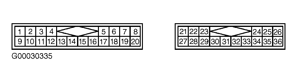 Courtesy of NISSAN MOTOR CO., U.S.A.