DTC P1320 - Ignition Signal
- Check Power Supply
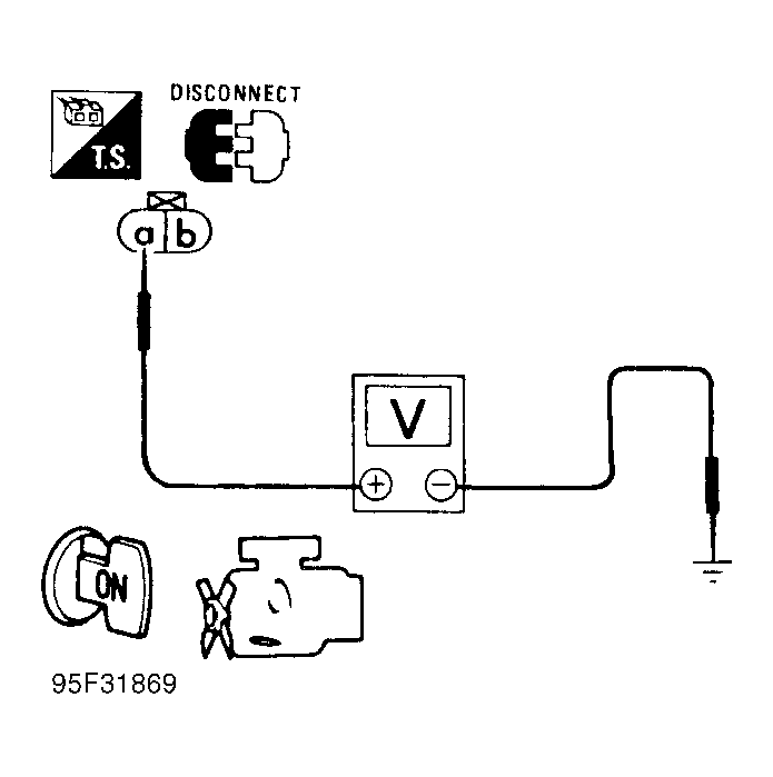
Start engine. If engine starts, go to step 5). If engine does not start, turn ignition off. Disconnect ignition coil harness connector. Turn ignition on. Measure voltage between ignition coil harness connector terminal "a" (Black/Red wire) and ground. Refer to Fig. Fig 3. If battery voltage is present, go to next step. If battery voltage is not present, repair Black/Red wire continuity between ignition coil and ignition switch.
- Check Ground Circuit
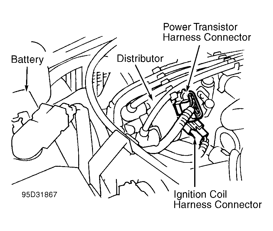
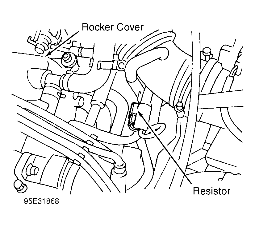
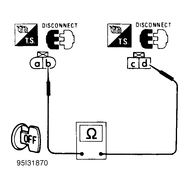
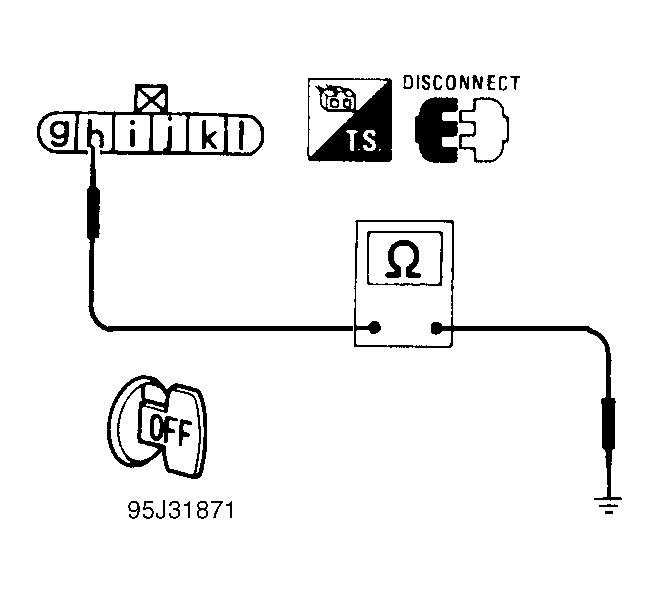
Turn ignition off. Disconnect power transistor harness connector. See Fig 1. Disconnect resistor harness connector. See Fig 2. Verify harness continuity between ignition coil connector terminal "b" and power transistor connector terminal "d", and between power transistor connector terminal "h" and engine ground. Refer to Figs. Fig 4 and Fig 5. If continuity is present, go to next step. If continuity is not present, repair harness or connectors as necessary.
- Check Output Signal Circuit
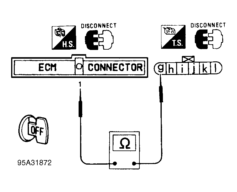
Turn ignition off. Disconnect ECM harness connector. See Figure. Verify harness continuity between ECM terminal No. 1 and power transistor connector terminal "g" (White wire). See Fig 6. If continuity is present, go to next step. If continuity is not present, repair harness or connectors as necessary.
- Check Input Signal Circuit
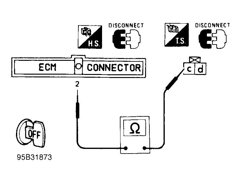
Turn engine off. Disconnect ECM harness connector and strip tape covering resistor. Verify harness continuity between ECM terminal No. 2 and resistor connector terminal "c" (Yellow/Red wire). See Fig 7. If continuity is present, go to next step. If continuity is not present, repair harness or connectors as necessary.
- Check Component
Disconnect resistor wiring harness connector. Measure resistance across connector terminals. If about 2200 ohms are present at 77°F (25°C), resistor is okay. Check ECM connector terminals for corrosion or damage. Repair as necessary and perform FINAL CHECK. If resistance is not as specified replace resistor.
- Disconnect ignition coil wiring harness connector. Measure resistance across connector terminals. About one ohm should be present. Check power transistor. See BASIC TESTING
article. Check ECM connector terminals for corrosion or damage. Repair if necessary and perform FINAL CHECK.
 Courtesy of NISSAN MOTOR CO., U.S.A.
 Courtesy of NISSAN MOTOR CO., U.S.A.
 Courtesy of NISSAN MOTOR CO., U.S.A.
 Courtesy of NISSAN MOTOR CO., U.S.A.
 Courtesy of NISSAN MOTOR CO., U.S.A.
 Courtesy of NISSAN MOTOR CO., U.S.A.
 Courtesy of NISSAN MOTOR CO., U.S.A.