Pinpoint Test A: The Speed Control Is Inoperative
- A1 CHECK THE SPEED CONTROL CABLE ATTACHMENT TO THE THROTTLE
- Key in OFF position.
- Remove the accelerator control splash shield. Inspect the speed control cable attachment. Check the speed control cable by pulling on the cable and noting the throttle movement.
- Is the speed control cable OK?
- Yes
: GO to A2.
- No
: REPAIR/RE-ATTACH the speed control cable. TEST the system for normal operation.
- A2 CHECK THE VOLTAGE TO THE SPEED CONTROL SERVO
- Disconnect: Speed Control Servo C122.
- Key in ON position.
- Measure the voltage between the speed control servo C122 pin 7, circuit 295 (LB/PK), harness side and the speed control servo C122 pin 10, circuit 57 (BK), harness side.
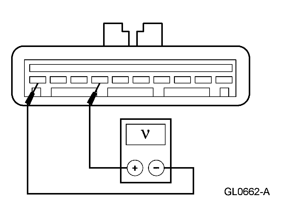 Courtesy of FORD MOTOR CO.
- Is the voltage greater than 10 volts?
- Yes
: GO to A4.
- No
: GO to A3.
- A3 CHECK THE SPEED CONTROL SERVO GROUND CIRCUIT 57 (BK)
- Measure the resistance between the speed control servo C122 pin 10, circuit 57 (BK), harness side and ground.
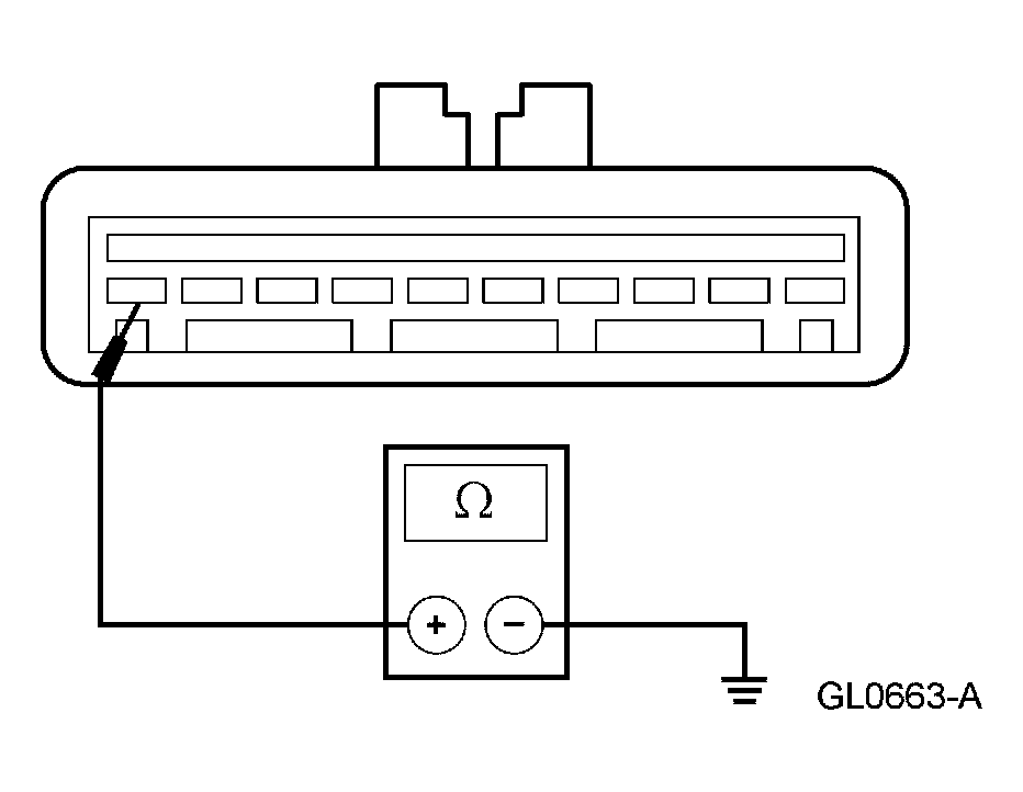 Courtesy of FORD MOTOR CO.
- Is the resistance less than 5 ohms?
- Yes
: REPAIR circuit 295 (LB/PK). TEST the system for normal operation.
- No
: REPAIR circuit 57 (BK). TEST the system for normal operation.
- A4 CHECK FOR BRAKE PEDAL POSITION (BPP) SWITCH INPUT WITH NO BRAKES APPLIED
- Key in OFF position.
- Measure the voltage between the speed control servo C122 pin 4, circuit 810 (RD/LG), harness side and the speed control servo C122 pin 10, circuit 57 (BK), harness side.
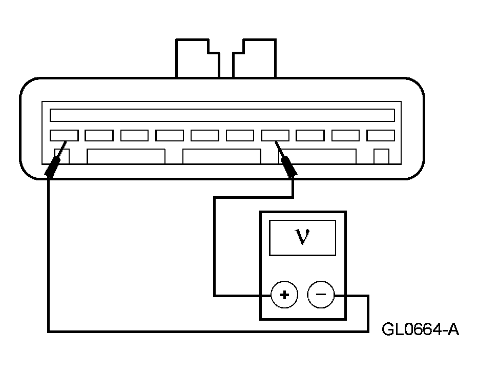 Courtesy of FORD MOTOR CO.
- Is any voltage present?
- Yes
: GO to A20.
- No
: GO to A5.
- A5 CHECK THE BRAKE CIRCUIT
- Measure the resistance between the speed control servo C122 pin 4, circuit 810 (RD/LG), harness side and the speed control servo C122 pin 10, circuit 57 (BK), harness side.
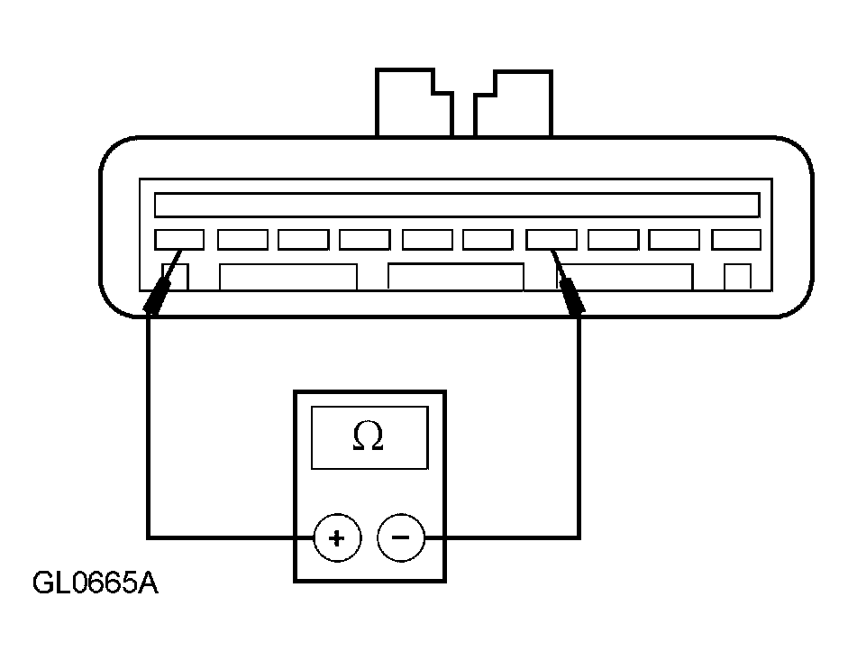 Courtesy of FORD MOTOR CO.
- Is the resistance less than 5 ohms?
- Yes
: GO to A6.
- No
: GO to A16.
- A6 CHECK THE DEACTIVATOR SWITCH INPUT TO SPEED CONTROL SERVO
- Measure the voltage between the speed control servo C122 pin 9, circuit 307 (BK/YE), harness side and the speed control servo C122 pin 10, circuit 57 (BK), harness side.
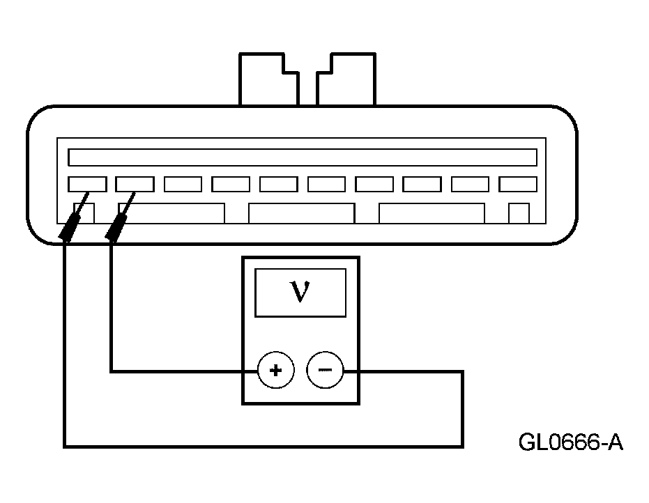 Courtesy of FORD MOTOR CO.
- Is the voltage greater than 10 volts?
- Yes
: GO to A9.
- No
: GO to A7.
- A7 CHECK THE DEACTIVATOR SWITCH
- Disconnect: Deactivator Switch C1025.
- Measure the resistance between the deactivator switch pins (component side).
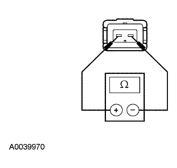 Courtesy of FORD MOTOR CO.
- Is the resistance less than 5 ohms?
- A8 CHECK DEACTIVATOR SWITCH POWER
- Measure the voltage between the deactivator switch, harness side and ground.
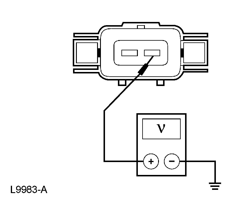 Courtesy of FORD MOTOR CO.
- Is the voltage greater than 10 volts?
- Yes
: REPAIR circuit 307 (BK/YE). TEST the system for normal operation.
- No
: REPAIR circuit 10 (LG/RD) or circuit 22 (LB/BK). TEST the system for normal operation.
- A9 CHECK FOR STUCK SPEED CONTROL SWITCH
- Measure the voltage between the speed control servo C122 pin 5, circuit 151 (LB/BK), harness side and the speed control servo C122 pin 10, circuit 57 (BK), harness side.
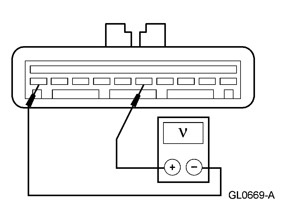 Courtesy of FORD MOTOR CO.
- Is any voltage present?
- Yes
: GO to A18.
- No
: GO to A10.
- A10 CHECK THE SPEED CONTROL SWITCH OPERATION
- Measure the voltage between the speed control servo C122 pin 5, circuit 151 (LB/BK), harness side and the speed control servo C122 pin 10, circuit 57 (BK), harness side, while pressing the speed control switch in the ON position.
Courtesy of FORD MOTOR CO.
- Is the voltage greater than 10 volts?
- Yes
: GO to A13.
- No
: GO to A11.
- A11 CHECK CIRCUIT 151 (LB/BK) FOR AN OPEN
- Disconnect: Clockspring C218a.
- Measure the resistance between the speed control servo C122 pin 5, circuit 151 (LB/BK), harness side and the clockspring C218a pin 1, circuit 151 (LB/BK) (6 pin) harness side.
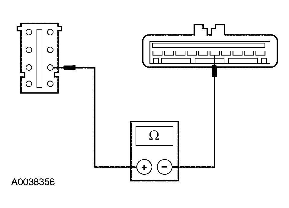 Courtesy of FORD MOTOR CO.
- Is the resistance less than 5 ohms?
- Yes
: GO to A12.
- No
: REPAIR the circuit. TEST the system for normal operation.
- A12 CHECK THE CLOCKSPRING FOR AN OPEN
- Remove the driver air bag. REFER to SUPPLEMENTAL RESTRAINT SYSTEM
.
- Measure the resistance between the clockspring C218a pin 1 (component side), and the top of clockspring pin 5 (5 pin) (component side).
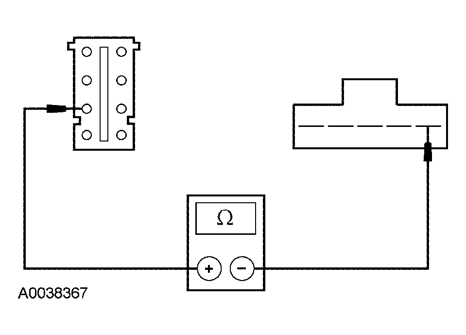 Courtesy of FORD MOTOR CO.
- Is the resistance less than 1 ohm?
- A13 CHECK THE SET/ACCEL SWITCH
- Measure the resistance between the speed control servo C122 pin 5, circuit 151 (LB/BK), harness side and the speed control servo C122 pin 6, circuit 848 (DG/OG), harness side, while pressing the speed control switch SET/ACCEL.
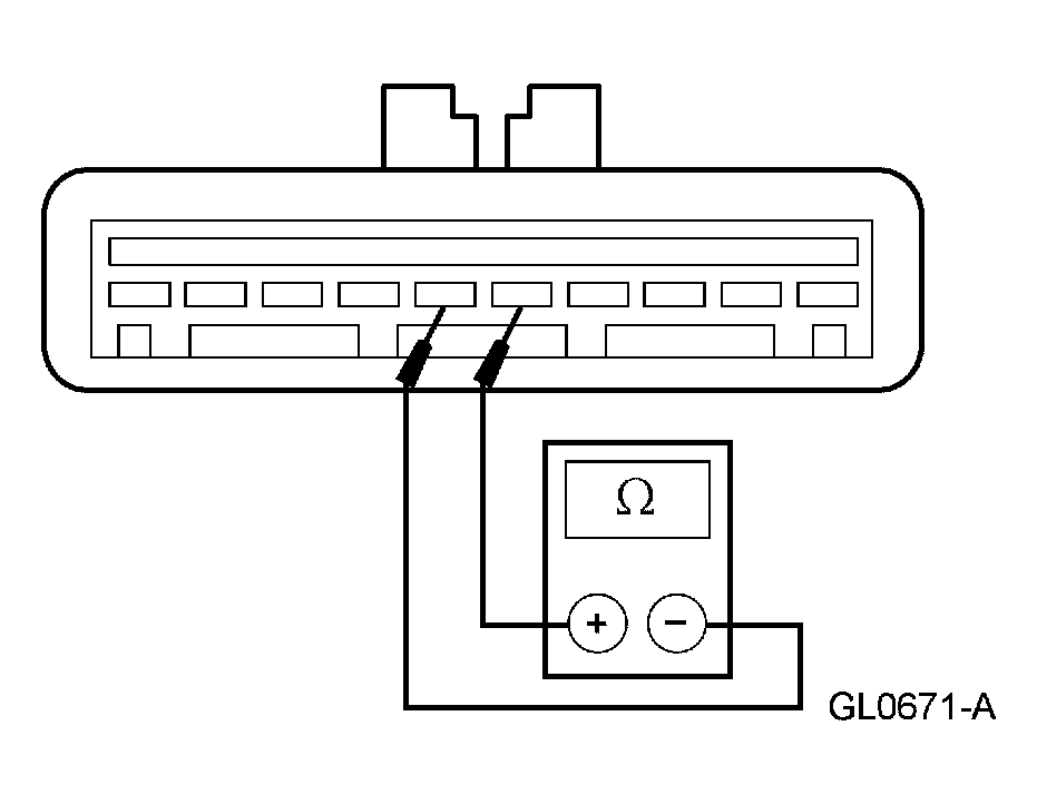 Courtesy of FORD MOTOR CO.
- Is the resistance between 612 and 748 ohms?
- Yes
: GO to A15.
- No
: GO to A14.
- A14 CHECK CIRCUIT 848 (DG/OG) FOR AN OPEN
- Measure the resistance between the speed control servo C122 pin 6, circuit 848 (DG/OG), harness side and the clockspring C218a pin 4, circuit 848 (DG/OG) harness side.
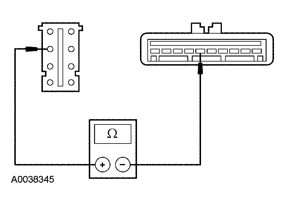 Courtesy of FORD MOTOR CO.
- Is the resistance less than 5 ohms?
- Yes
: INSTALL a new speed control switch. REFER to SPEED CONTROL SERVO SWITCH in this article. TEST the system for normal operation.
- No
: REPAIR the circuit. TEST the system for normal operation.
- A15 CHECK THE SPEEDOMETER
- Check the speedometer for correct operation by driving the vehicle.
- Does the speedometer operate correctly?
- A16 CHECK CIRCUIT 676 (PK/OG) FOR AN OPEN
- Disconnect: Brake Pedal Position (BPP) Switch C278.
- Measure the resistance between the BPP switch C278 pin 1, circuit 676 (PK/OG), harness side and ground.
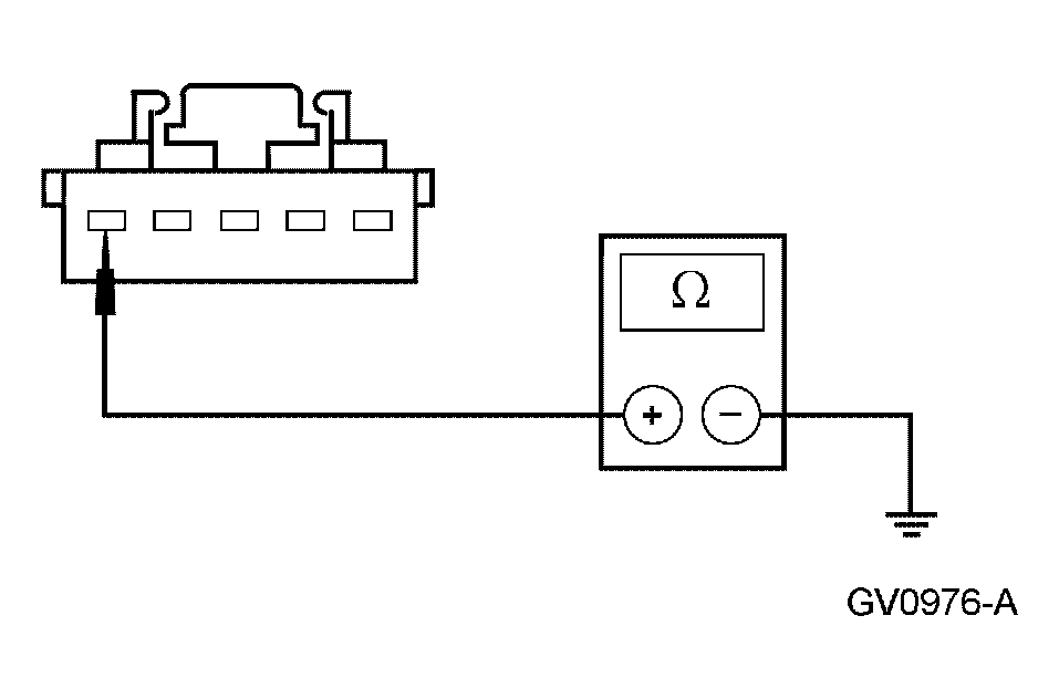 Courtesy of FORD MOTOR CO.
- Is the resistance less than 5 ohms?
- Yes
: GO to A17.
- No
: REPAIR circuit 676 (PK/OG). TEST the system for normal operation.
- A17 CHECK THE BRAKE PEDAL POSITION (BPP) SWITCH
- Remove the BPP switch. REFER to EXTERIOR LIGHTING
.
- Carry out the BPP Switch component test. Refer to COMPONENT TEST in this article.
- Is the BPP switch OK?
- Yes
: REPAIR circuit 22 (LB/BK). TEST the system for normal operation.
- No
: INSTALL a new BPP switch. TEST the system for normal operation.
- A18 CHECK THE SPEED CONTROL SWITCH
- Key in OFF position.
- Remove the driver air bag. REFER to SUPPLEMENTAL RESTRAINT SYSTEM
.
- Connect: Restraint System Diagnostic Tool 418-F088 (105-R0012) or equivalent.
- Connect the battery. REFER to BATTERY, MOUNTING AND CABLES
.
- Disconnect: Speed Control Switches.
- Key in ON position.
- Measure the voltage between the speed control servo C122 pin 5, circuit 151 (LB/BK), harness side and the speed control servo C122 pin 10, circuit 57 (BK), harness side.
Courtesy of FORD MOTOR CO.
- Is voltage present?
- Yes
: GO to A19.
- No
: INSTALL a new speed control switch. REFER to SPEED CONTROL SERVO SWITCH in this article. TEST the system for normal operation.
- A19 CHECK CIRCUIT 151 (LB/BK) FOR SHORT TO POWER
- Key in OFF position.
- Disconnect: Clockspring C218a.
- Key in ON position.
- Measure the voltage between the speed control servo C122 pin 5, circuit 151 (LB/BK), harness side and the speed control servo C122 pin 10, circuit 57 (BK), harness side.
Courtesy of FORD MOTOR CO.
- Is voltage present?
- Yes
: INSTALL a new clockspring. REFER to SUPPLEMENTAL RESTRAINT SYSTEM
. TEST the system for normal operation.
- No
: REPAIR the circuit. TEST the system for normal operation.
- A20 CHECK BRAKE PEDAL POSITION (BPP) SWITCH INPUT CIRCUITRY FOR SHORT TO POWER
- Key in OFF position.
- Disconnect: BPP Switch C278.
- Measure the voltage between the speed control servo C122 pin 4, circuit 810 (RD/LG), harness side and the speed control servo C122 pin 10, circuit 57 (BK), harness side.
Courtesy of FORD MOTOR CO.
- Is voltage present?
- Yes
: REPAIR circuit 810 (RD/LG). TEST the system for normal operation.
- No
: INSTALL a new BPP switch. REFER to EXTERIOR LIGHTING
. TEST the system for normal operation.
- A21 CHECK THE SPEED CIRCUITRY FOR AN OPEN
- Key in OFF position.
- Disconnect: Anti-lock Brake Control Module C135.
- Measure the resistance between the speed control servo C122 pin 3, circuit 679 (GY/BK), harness side and the anti-lock brake control module C135 pin 11, circuit 679 (GY/BK), harness side.
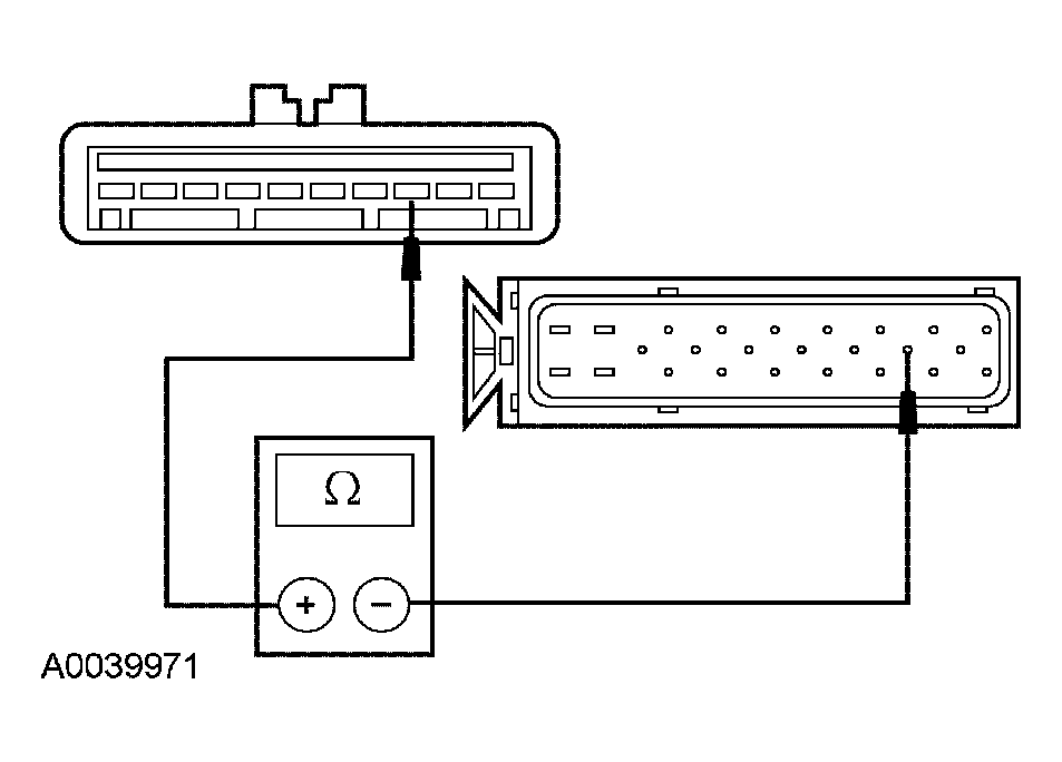 Courtesy of FORD MOTOR CO.
- Is the resistance less than 5 ohms?
- Yes
: GO to A22.
- No
: REPAIR the circuit. TEST the system for normal operation.
- A22 CHECK THE SPEED CONTROL INDICATOR CIRCUITRY FOR AN OPEN
- Key in ON position.
- Disconnect: Anti-lock Brake Control Module C135.
- Connect a fused (10A) jumper wire between the speed control servo C122 pin 1, circuit 203 (OG/LB), harness side and ground, while observing the speed control indicator.
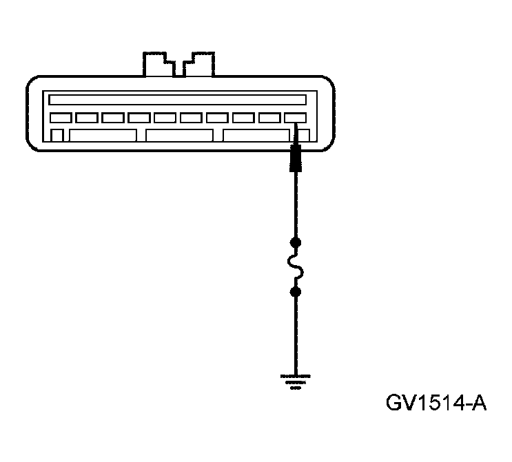 Courtesy of FORD MOTOR CO.
- Is the speed control indicator illuminated?